Electrical Basics – How To Wire An Electrical Outlet
Today I want to share yet another “electrical basics” post with you. This one is super simple, but it’s one that a few of you have asked for specifically — how to wire an electrical out. If you’ve never installed an electrical outlet before, and have been afraid to take that face plate off and see what’s under there, I think you’ll be surprised at how easy this is.
And since this is probably the most common situation you’ll find, I’ll be demonstrating how to install an electrical out in the middle of a circuit.
First and foremost, before doing anything with switches or outlets or lighting or any other electrical thing, you need to be sure that the power is switched off at the breaker box. If you don’t know how to do this, or don’t know which circuit breaker feeds what area of your house, or you don’t know how to use a circuit tester, DO NOT PROCEED.
After you’ve switched the circuit breaker off, always be sure to test the circuit with a circuit tester.
In my particular case, I didn’t have to do any of that because none of the wiring for this room has even been wired to the breaker box yet. If I go into the closet where my breaker box is, I just have five wires for the five circuits for my studio hanging down inside the closet from the attic, and none of them are anywhere near the breaker box yet. Wiring those to the breaker box will be the last step. Anyway, moving on…
I’ve explained this before in a previous post, but to refresh your memory, a circuit is simply a series of outlets and/or switches that receive their power from one circuit breaker in the breaker box.
The circuit I wired last night is the this one, where the wire comes from one circuit breaker in the breaker box in the guest bedroom closet, travels across the attic, and goes to the outlet labeled #1. From there, it goes to #2, and #3, and so on.
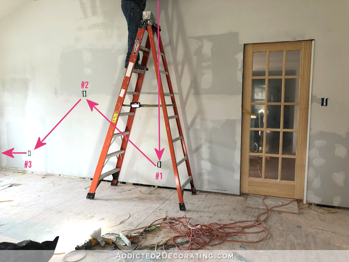
And in the pictures on this post, I’ll be wiring the outlet labeled #2 in the photo above. So it’s receiving it’s power from the outlet #1, and then sending power on to outlet #3 in the circuit.
In the junction box, I have two wires. As I explained before, I always label my wires, so you can see one says “power in” (meaning it’s coming from outlet #1) and the other says “power out” (meaning that it’s heading to the next outlet in the circuit, outlet #3).

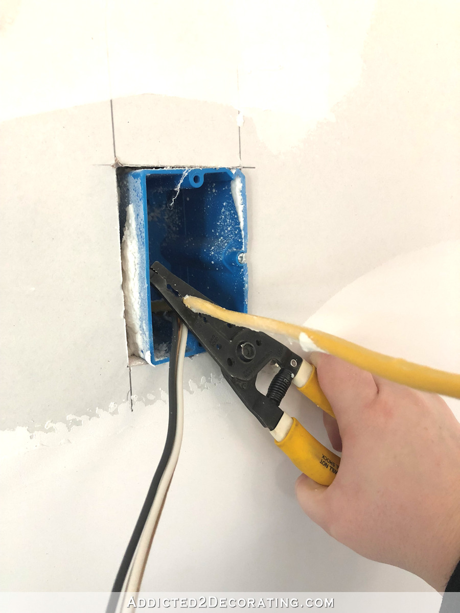
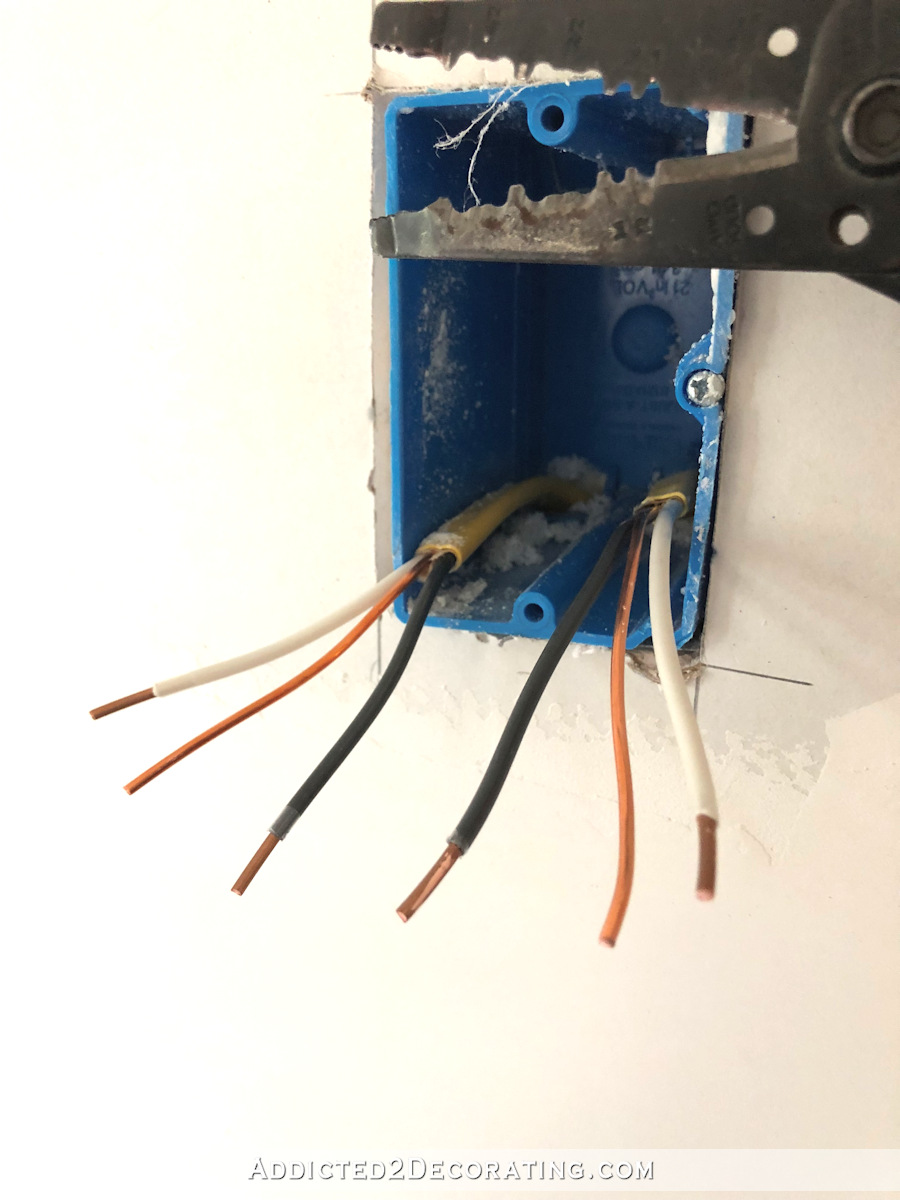
The first step is to strip the yellow sheathing off of the wires, and I use this tool for that…

The circled areas are specifically for stripping this outside sheathing off of 14/2 and 12/2 wire. My wire is 12/2, so I use the larger one.
I try to cut the sheathing as far into the box as possible, which generally leaves about an inch or so of the sheathing visible in the box.
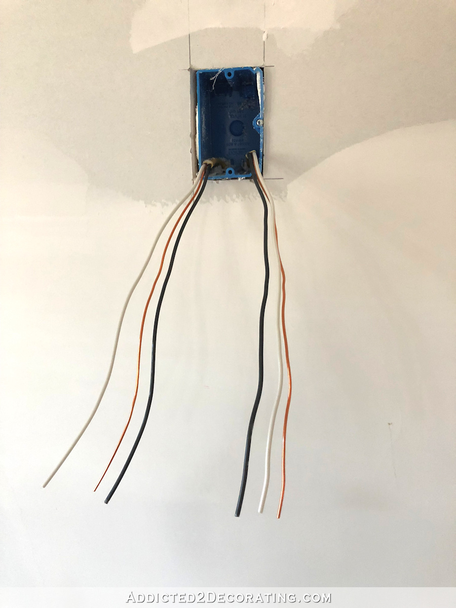
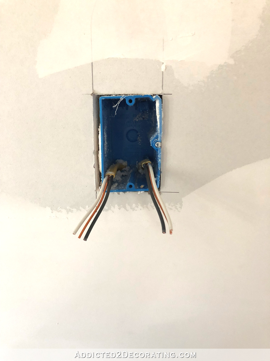
And once the yellow sheathing is stripped off (the wire cutters cut it very easily, and then you just pull it off), there are six separate wires exposed — two black, two white, and two bare copper.
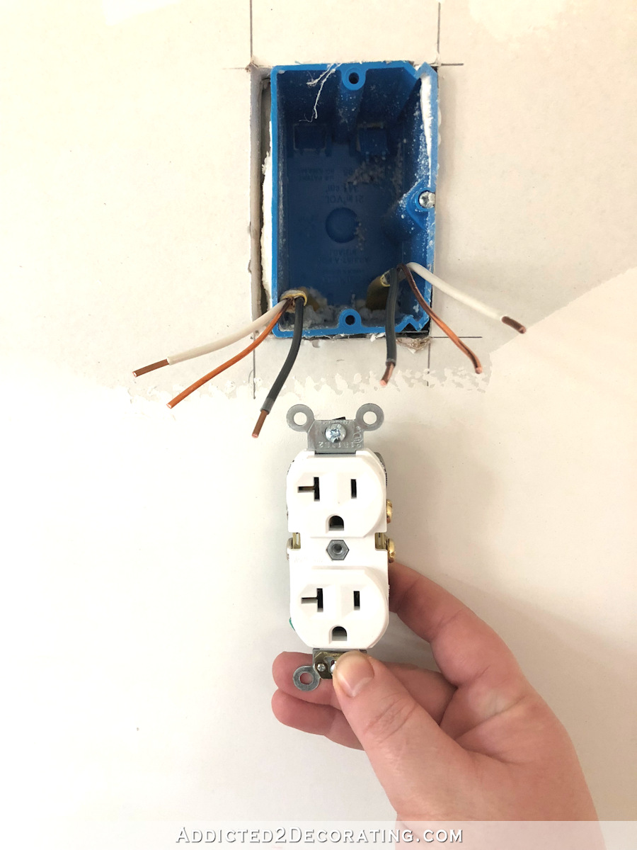
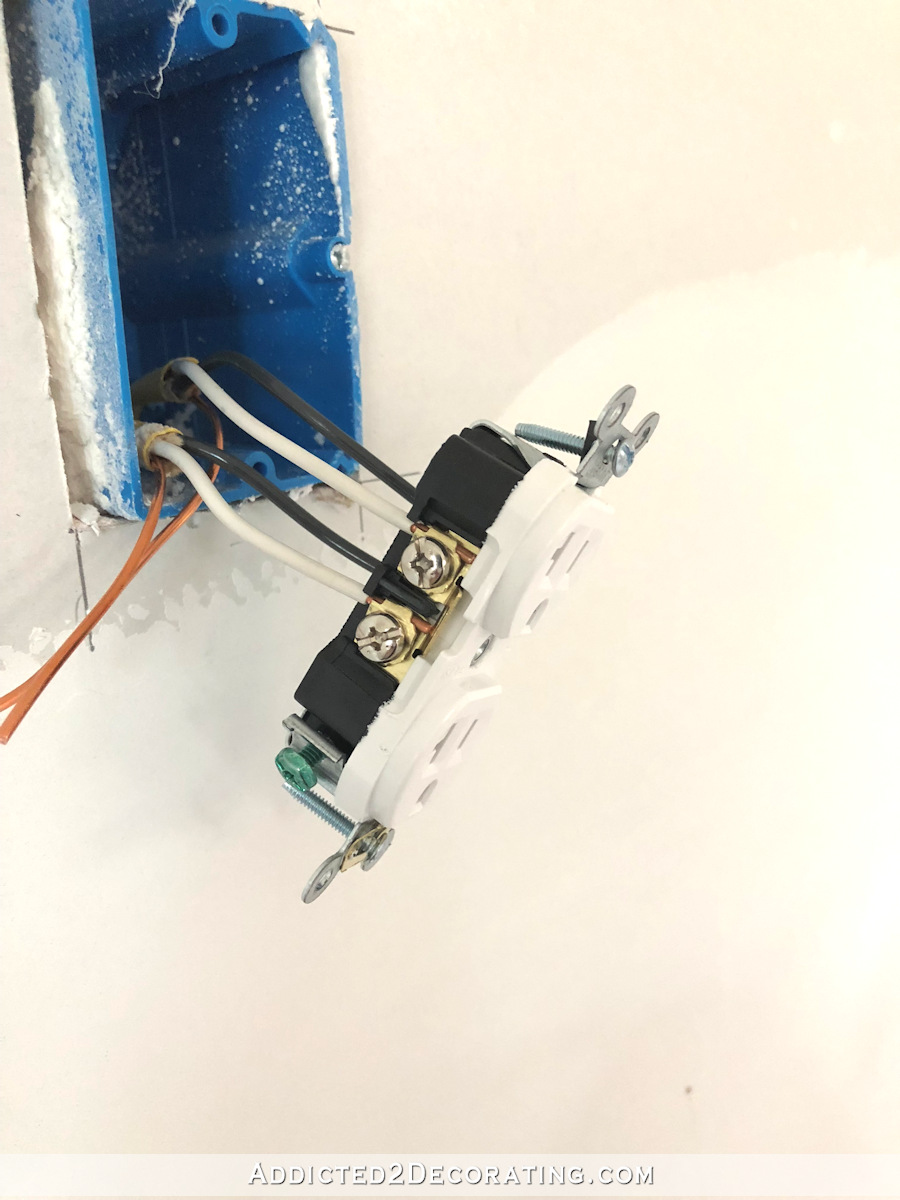
The outlets that I use are these labeled “back and side wire outlet.”

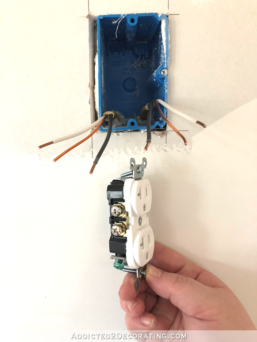
When working with 12-gauge wire, I use these exclusively. They cost a bit more than the cheap outlets you can buy in the bulk contractors packs, but these save so much time and are a lot less work because under the terminal screws, they have these little metal plates…

If you have an outlet that doesn’t have those little metal plates under the terminal screws, that means you have to bend the ends of your wire into little hooks or loops and wrap the wire around the screws. That’s not a big deal when dealing with 14-gauge wire, but it’s such a frustrating headache when dealing with 12-gauge wire.
So I opt for these outlets that have those little plates/clamps under the screws. This allows you to simply insert the wire straight under the plate/clamp and tighten the screw. No having to hook the wire and wrap it around the screw. This is so much easier, and such a time saver!
So back to the box, I cut the excess wire off so that what’s left is about four inches of wire sticking out past the front of the box. That gives me a total of about 7-8 inches of wire to work with.
That’s a guesstimate. It might be a bit more or less than four inches past the front of the box. Just keep in mind that if you cut them too short, you’re kind of up a creek, and it’ll make things really difficult to wire. If you leave them too long, it’s hard to get all of that wire tucked in the box when you’re done.
Next, I use the same wire strippers, and use these smaller areas to strip the individual wires. There’s one for 14-gauge wire, and one for 12-gauge wire. Mine is 12-gauge, so that’s the one I used.

I stripped about 3/8 inch from the ends of the wires.
You do not have to guess at how much to strip from the ends of the wires. Every single outlet or switch that you purchase will come with a strip gauge on the back of the outlet or switch (or if it’s not there, it’ll be inside the packaging) telling you exactly how much you need to strip for that particular outlet or switch.
With the wires cut and stripped the appropriate amount, I’m ready to wire up the outlet.
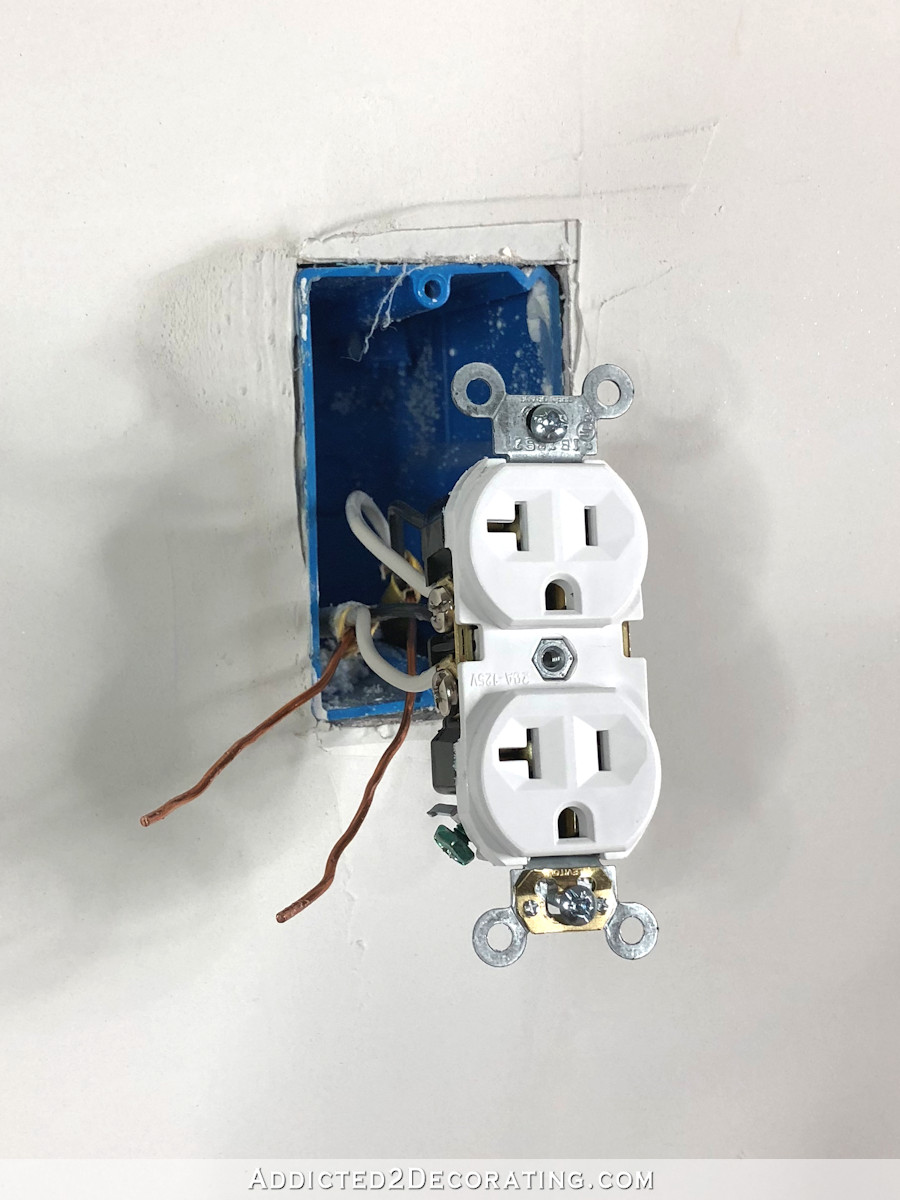
On one side, you’ll find silver screws. Those are the neutral terminals that the white (neutral) wires go to.
On the other side, you’ll find brass screws. Those are the terminals where the black (hot) wires will go.

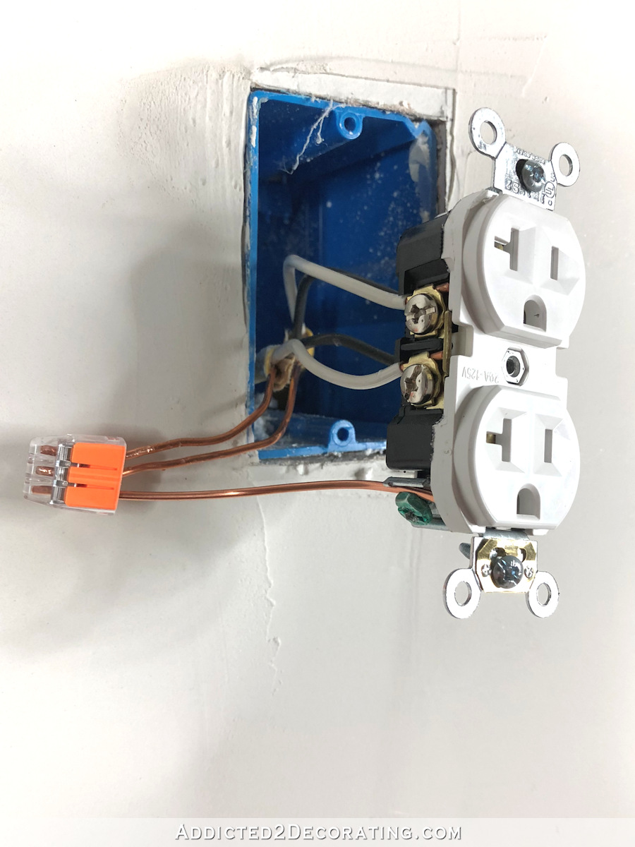
So on the right side, where the brass screws are, I simply insert the stripped ends of the black wires underneath those metal plates/clamps, and tighten the screws to hold the wires in place.
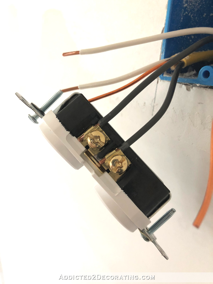
Remember how I labeled my wires (i.e., power in, power out)? I always put the one labeled “power in” on top, and the ones labeled “power out” on bottom. That way I always know which direction a particular wire is going, and there’s no confusion if I need to get in there and do something in that junction box at a later date.
And then repeat that process on the other side with the white wires going to the silver terminals.
And again, if you don’t purchase the outlets with the little plates/clamps under the screws, and all you see are screws there, then you just have to form a little loop in the end of the wire and wrap it around the screw. Such a pain. 😀
So now I have my black (hot) wires connected, and my white (neutral) wires connected. That just leaves the ground wires.
I like to use these push-in connectors, which you can use in place of wire nuts. Because again, working with uncooperative 12-gauge wire makes me want to cuss, so I’ve found that these make the job so much easier than all of that twisting and screwing on wire nuts.
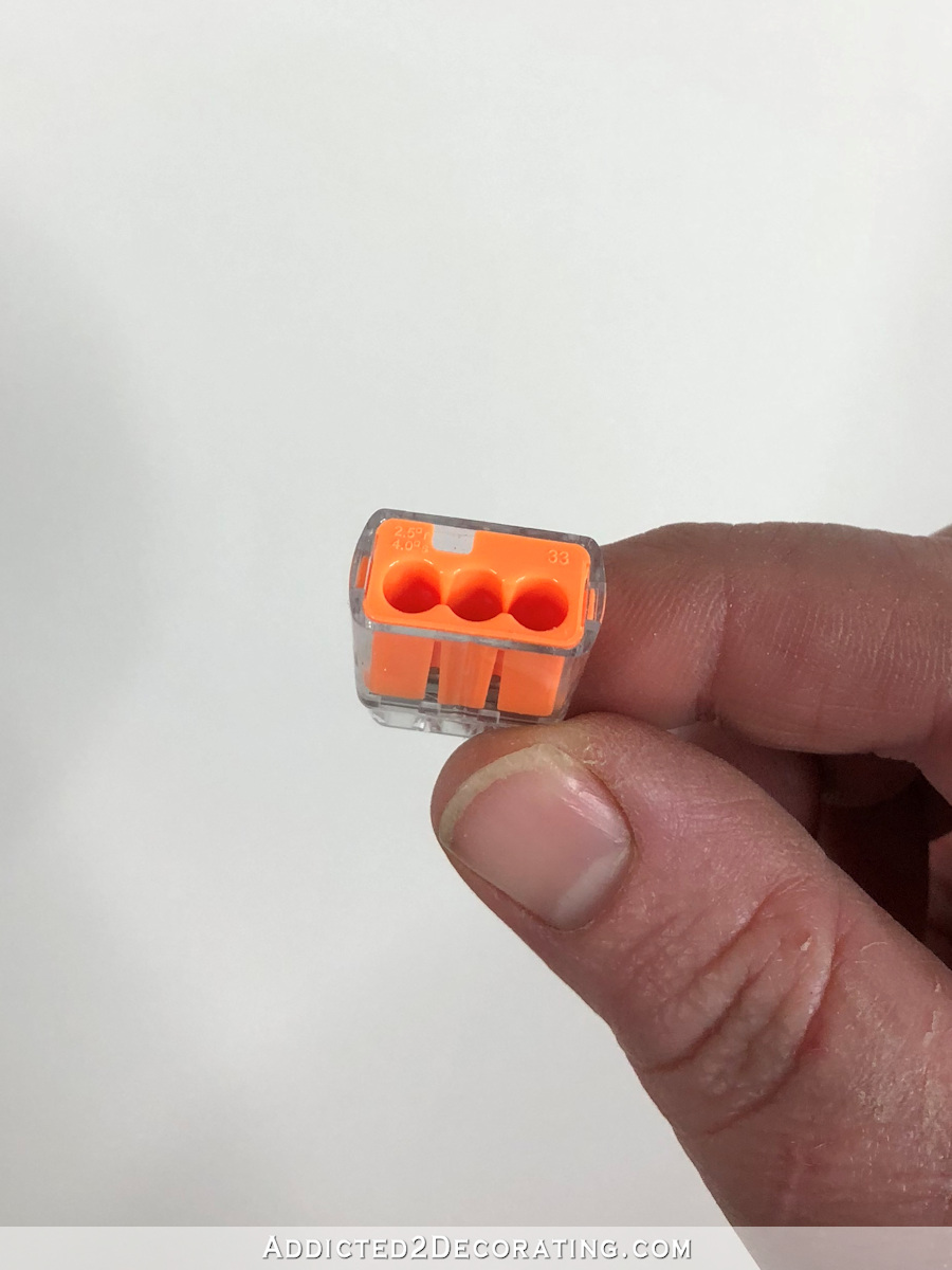
I start by attaching the two ground wires together using a push-in connector.
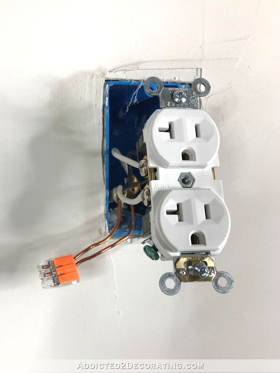
That connected the ground wire from the wire coming into the box, and the ground wire from the wire leaving the box and going to the next outlet. But you’ll notice that that did nothing to actually ground the outlet because there’s still nothing going to the little green screw on the outlet.
So to remedy that, I cut a small piece of wire about six inches long…
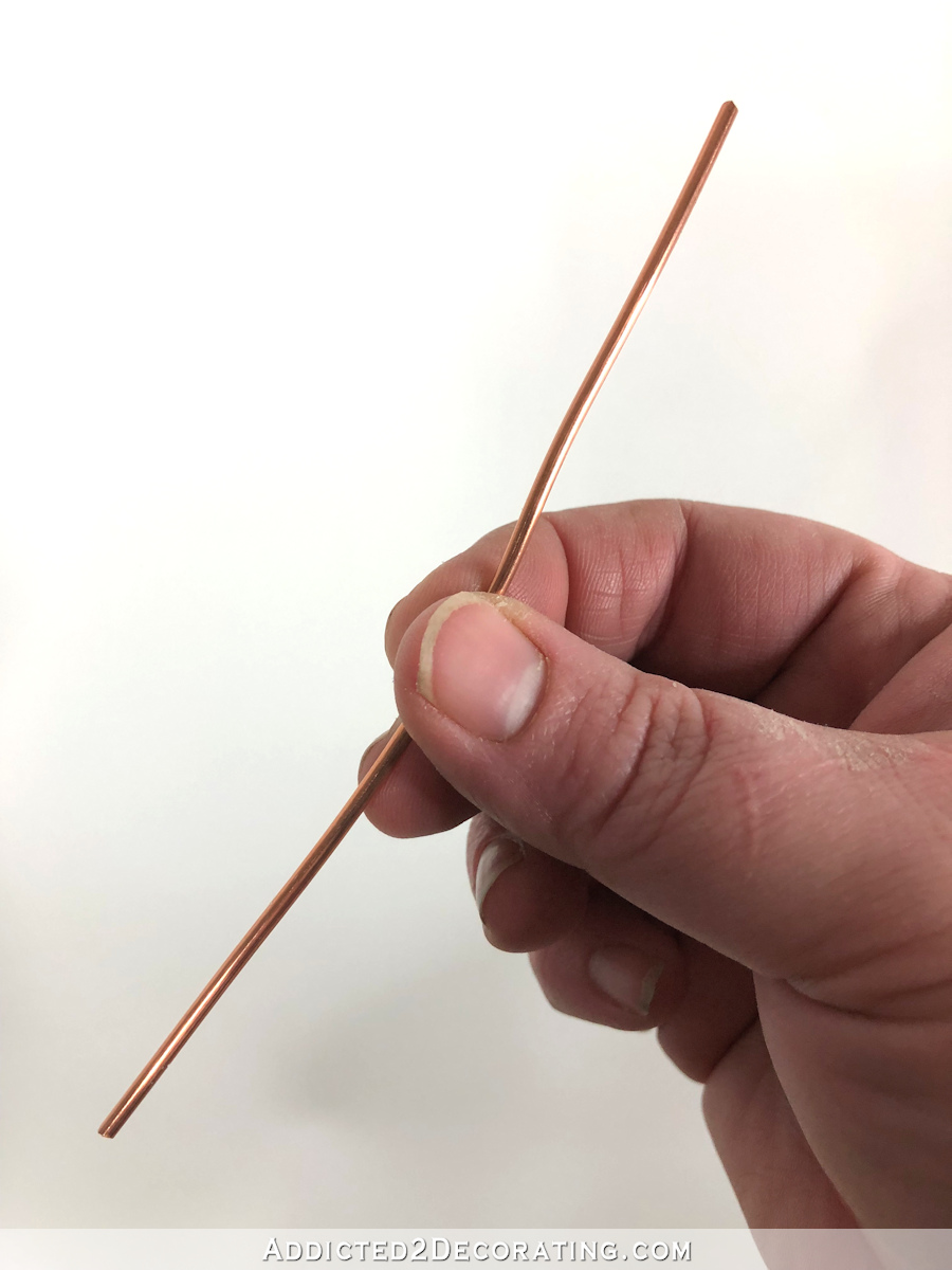
…and I inserted one end into the push-in connector to create what’s called a “pigtail.”
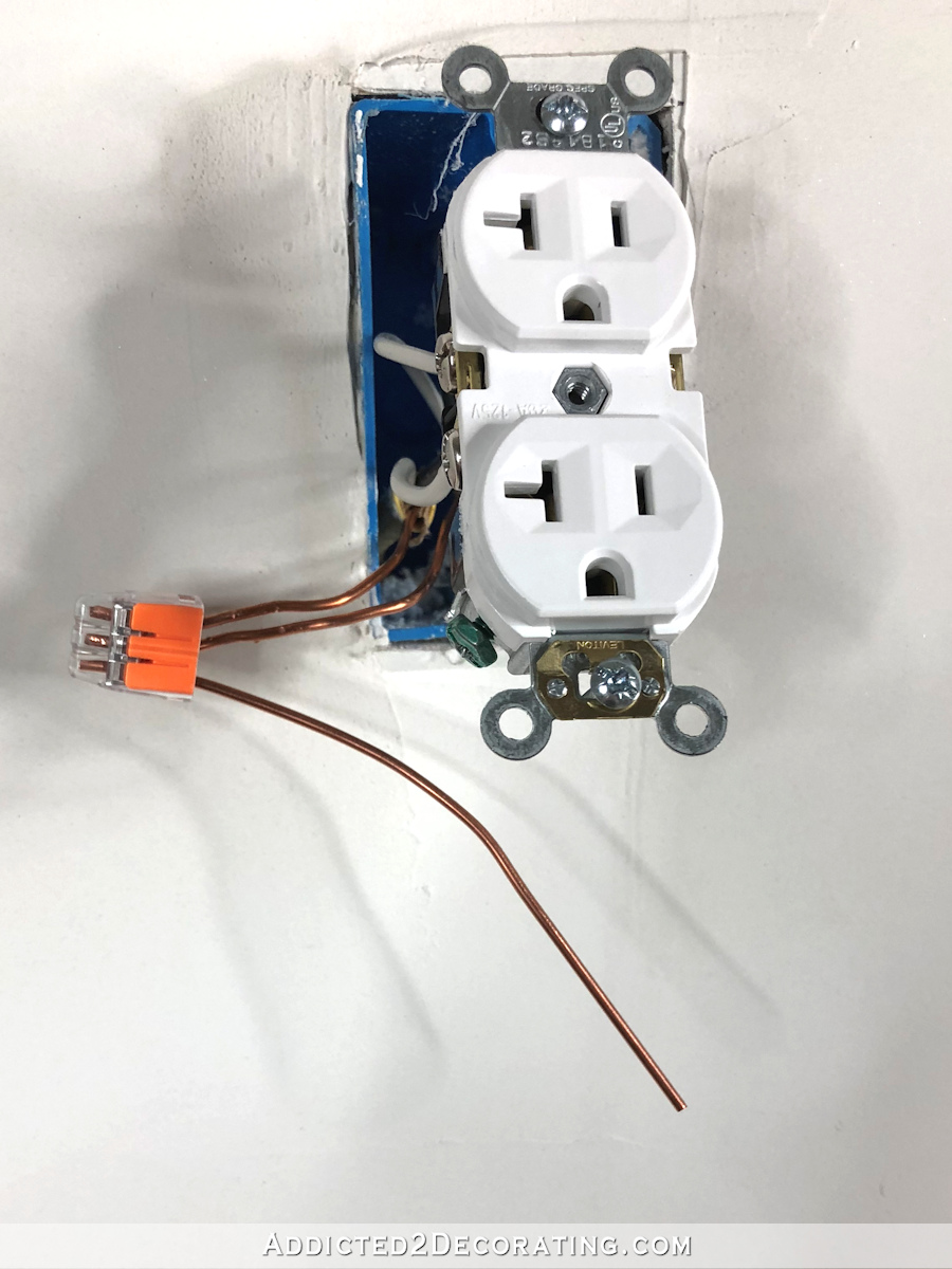
And then the other end of that pigtail gets connected to the green/ground screw on the outlet.
That screw doesn’t have a plate/clamp on it, so I generally do go ahead and make a hook in the end of the wire and wrap it around. But I noticed that it has a little area that my cheaper outlets don’t have where the wire can easily slip in and be held very tightly when the screw is tightened. There are no specifics on the written instructions that come with this outlet about this, but I tested it by pulling very tightly on the wire and it seemed to hold perfectly like this. While this seems to hold very securely, I’d recommend creating a bend at the end of the wire and wrapping it around the screw.
And then the outlet is ready to be screwed into place in the junction box. This is probably the hardest part of the whole process if you’re working with 12-gauge wire. I’m telling you that those things just do not want to bend and cooperate, so it might take a bit of gentle wrestling to get everything in there far enough to get the outlet screwed onto the junction box, but just be firm but gentle, and a little patient, and it’ll get there.
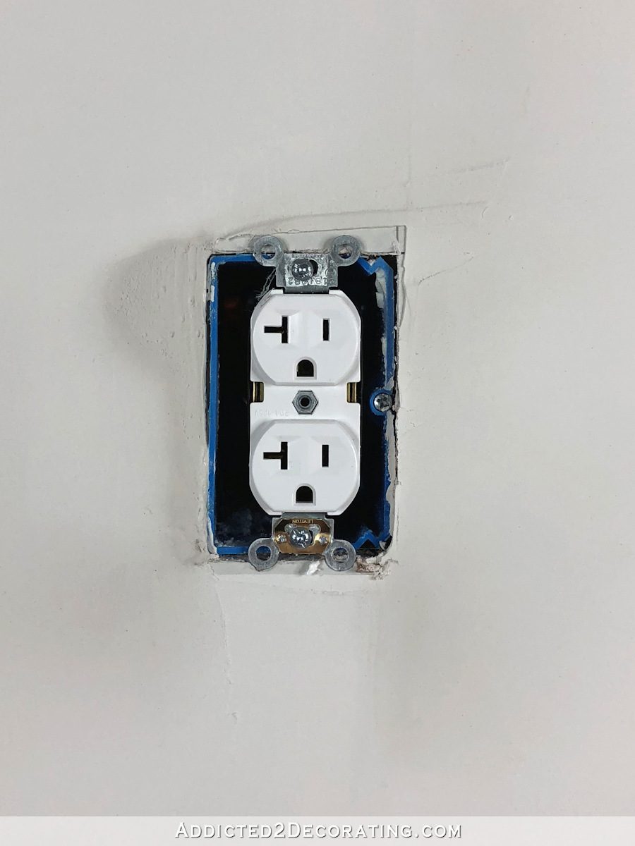
But that’s it! Wiring an electrical outlet is really so simple! And once it’s all wired and screwed into place, you can turn the circuit breaker back on and test the outlet to be sure that it’s all working properly. Easy peasy! And of course, you’ll want to add a face plate to finish up the job. I’m not going to do that right now because the drywall guys are still taping and mudding, and when they’re done, I’ll be priming and painting. I’ll add face plates when the walls are finished.
I was also going to show how to wire a light switch today, but this post got a little long. So I’ll save the switch wiring post for later.

Addicted 2 Decorating is where I share my DIY and decorating journey as I remodel and decorate the 1948 fixer upper that my husband, Matt, and I bought in 2013. Matt has M.S. and is unable to do physical work, so I do the majority of the work on the house by myself. You can learn more about me here.


I love you! Seriously! This stuff should be part of a basic adulting course. I know that “home ec” is theoretically that course. But, really, basic car maintenance (like oil changes), time value of money (like save up for your car instead of financing it), and this stuff should really be part of the course. I have a master’s degree, but don’t know jack about how the electricity flows through my house. What kind of sense does that make?!?!
Your next venture needs to be a You-Tube channel. There are tons of You-Tube videos out there, many where the person isn’t even in the video. You already have your scripts written out! You just need to make the videos!
Completely agree. I am in awe of all the stuff that Kristi can do. Would also love to see more videos from her.
Thank you! I’ve done this before but would love a quick how to reference for future installation of: ceiling lights/chandeliers
You’re awesome, thanks always!
I’m just curious as to why you’re using 12/2 wire rather than 14/2? My apologies if you explained it somewhere else.
12/2 is pretty standard for all residential wiring these days. I know some people still use 14/2, and in my humble opinion, it’s still perfectly fine for residential use. But 12/2 is the standard now.
Ah, makes sense. Where I live (in Canada), I think 14/2 is still pretty standard for regular wiring. That’s what we’ve been using anyway, for the large amounts of rewiring we’ve been doing in our house.
12/2 allows more amperage. That means you can p,up in stuff that has a high draw (like your iron) without popping the circuit.
I just wired two bedrooms of a 1938 house my husband and I gutted. We are redoing the plumbing and electrical systems, which means the walls came a tumbling down.
That was supposed to say plug in.
I actually th8nk I could follow your directions and do this! Thank you! My only question is, when you said you used electrical tape, was it around the two ground wires together?
I made two full laps around the sides of the outlet, so it covered all five screws.
You explain it so well. I should have known it was seriously hard to do. I am going to print your instructions out on my printer and put it in my house manual binder. I have some cream plugs that I would like to be white.
My mum has always done the electronic work this including putting in ceiling fans, etc. She is only 4’11”. She is in her late 70s now and I don’t want her to fall and have to get another 21 steel pins put in her shoulder/arm. She informed us that she wasn’t climbing and just fell over the dog (I didn’t buy this, but my sister did).
I’ve never wired a new outlet, but I’ve always switched out the outlets in my houses with shiny new white ones. I think it makes such a difference and makes everything look so clean!
I once stupidly switched out a light switch without turning off the breaker (just completely forgot). When I was struggling with the wires to get it back into the box, two of the screws hit the sides of the metal junction box. Sparks flew, things popped, lights went off, I screamed. Now I have my tester with me at all times and I check three or four times before I get started, haha!!
We were ripping out a pony wall a few years ago, and didn’t realize there were wires in the wall. I think we must have just looked at the one side of the wall or something. Oops. That was dumb. My husband yanked on a stud and ripped the wire out of the outlet. Something popped and sparks flew. Yikes! We’ve definitely been more careful with wiring since!
Yikes! One thing is for sure. Once you’ve made a careless mistake with electricity, you will never do it again!! haha
I’ve watched several videos on electrical wiring before I received your post and lemme tell ya you REEEAAAALLLLLY made it super easy to understand. I feel 100% confident that I can do this project myself when the time comes! I’m going to print this out and put it in my binder so when the time comes I’ll have it handy. Thank you for giving me the confidence I needed. Can’t wait to see what you do next 🙂
Ditto on how great it is to have this information absent all the man-splaining I’ve had in the past when asking a simple question. Like Olivia, I want to replace my 1980s cream outlets with white and this tutorial is PERFECT. Especially good to know about those outlets. I can’t wait until tomorrow for the switches tutorial.
Thank you, thank you, thank you!
That is good info but you should always wrap the two bare grounds together before putting on of the on the screw. You get a better connection that way. I always hook up the ground first then the neutral wire than the black. When disconnecting do black then white then ground. As an electrician this protects you if for some reason the power gets turned on or there is a feedback. Great info.
Thank you! That’s very helpful. I can see how you would get better connection wrapping the grounds together first, and then putting one on the screw. I’ll do that with the rest of the outlets I have to wire this weekend.
My husband is a contractor in San Francisco. My question is: Don’t you need to get permits before doing electrical, plumbing and carpentry work? When he is done with the work, it has to go through a city inspector and be signed off. I have not seen you mention every going through the city for these requirements.
I do mention quite often that these requirements are different from state to state, and even from one city or county to the next. You should always contact your local building permit office to see what’s required in your specific area, and not rely on that type of info from someone who lives in a different state or even a different city in your same state.
And generally when you hire a contractor (as I have done on this area) they are the ones who that for you. The homeowner doesn’t do that for the contractor.
Now with that said, this post was just for general information purposes because I’ve had several people ask me how to swap out their outlets (i.e., from antique white to white). I’ve never heard of a homeowner getting a permit to swap out outlets when there’s already a box and wiring there.
While I appreciate all of the work put into this post, as a 30+ year Electrician I must point out some points of common practice, as well as some code violations. I’ll start with #12 is not the new normal in residential buildings. The average electrical box (3x2x3-1/2) is 18 cubic inches. For every colored wire count 1, for all of the ground wires count 1, and for every device count 1. In the pictures show this equals 4+1+1 or 6 conductors. For #14 each is 2 CI and for #12 it’s 2.25 CI. So using #14 would use up 12 CI while the #12 uses 13.5 CI. Adding one more #12 cable would max out the box, while you could ad 2 more #14 cables. Next, electrical code requires the conductors to extend 6″ past the front of the box, so only 4″ is a code violation. I would also note here that by pigtailing the wires together you only end up with a black, white, and ground going to the outlet. This makes the installation of the outlet into the box much easier with less stress to the outlet terminals. Next is that ground splice, A crimp or wirenut is required by code, simply wrapping them together is not the right way to do it. When it comes to that ground screw, as well as any other screw terminal like it, the wire is required by code to wrap 3/4 of the way around the screw and in the direction the screw is turned to be tightened, such as twisting to the right. Lastly regarding wrapping tape around the outlet, there’s a reason Electricians don’t do it…it’s flammable. That’s right, by wrapping the tape you’re introducing a flammable material to the inside of the box, effectively defeating the entire reason for the box in the first place. I’m not trying to bash or embarrass anyone, I’m just try to help make sure the work is done correct and safe.
Thank you for the info. I did make changes to the post. But I will also disagree with you about the 12/2 wire. Maybe it’s a regional thing, specific to Texas, or even to my city/county, but in my area (central Texas), you will not find a new build house that’s being wired with 14/2 wire. It’s all 12/2 wire, and in fact when I went to Home Depot a couple of years ago to purchase some 14/2 wire for a project, I specifically asked the guy (a retired electrician who worked in this area) if I could use 14/2 to wire my room, and he said, “Well, as long as you don’t plan to have it inspected. But an inspector will require 12/2.” So again, maybe that’s a regional-specific code, but it doesn’t seem like it. Every time I see a new build house on TV, on blogs, etc., all I see is yellow (12/2) Romex. I don’t see the white (14/2) anymore on new construction.
Also…
NEC 2017 300.14 Length of Free Conductors at Outlets, Junctions, and Switch Points.
At least 150 mm (6 in.) of free conductor, measured from the point in the box where it emerges from its raceway or cable sheath, shall be left at each outlet, junction, and switch point for splices or the connection of luminaires or devices. Where the opening to an outlet, junction, or switch point is less than 200 mm (8 in.) in any dimension, each conductor shall be long enough to extend at least 75 mm (3 in.) outside the opening.
Exception: Conductors that are not spliced or terminated at the outlet, junction, or switch point shall not be required to comply with 300.14.
__________________________________
That does NOT say measured from the front of the junction box. It’s measured from where the conductors emerge from their raceway or cable sheath inside the box.
I’m aware of the wording of article 300.14 of the NEC code. My comment was focused the cable sheaths as shown in your pictures which come to the front of the box. So in the pictures you have posted there is not a minimum of 6″ of conductors exposed.
Kristi;
I have a question about replacing existing outlets & switches. Is it important to know which wires are the PowerIN and which are the PowerOut in the circuit? In other words, what happens if I guess wrong? Is there any way to tell which are IN and which are OUT?
No, it’s really not necessary. I just like to know because I’m a bit obsessive about knowing stuff like that. 😀 But if you’re not sure, you can still change out your outlets. When you turn the power off and remove the old outlet, you should be able to see that one set of hot, neutral and ground wires are sheathed together, and another set of hot, neutral and ground wires are sheathed together. It’s not necessary to know which one is feeding power to that outlet, and which one is sending power to the next outlet. As long as you get both hot wires, both neutral wires, and both ground wires connected properly, it’ll be fine.
I don’t know if I’ll ever need to use this but I love that your instructions on anything are always one of the best out there.
Hi Kristy! Thanks for the awesome tutorial! Just curious if you are replacing or working with existing outlets and need to push them forward, e.g. because of adding a tile backsplash, how would you complete? Thanks again!
There are small plastic spacers made for this purpose. They attach to the two screws that hold the outlet in place. They come in strips with about ten spacers attached together, and they fold like an accordion. So you can fold as many as you need together (you’ll often need two or three) and place on the screw. Just keep in mind that you might need to purchase longer screws.
Excellent, easy to understand especially with closeup pictures. Thanks for the time and effort you put into this – very much appreciated.
I wish you would do a video on this. It’s so clear this article, you would think it is a video. Thank you so much for sharing this information.