Electrical Basics – Wiring A Basic Single-Pole Light Switch
It has taken me a little longer than I thought, but I’m finally ready to show y’all how to wire a basic single-pole light switch. But first, a few explanations and caveats.
First of all, please understand that I’m sharing this, along with the other few posts about electrical stuff, not because I’m hoping you’ll go out and rewire your entire house. In fact, I realize that many (probably most) of you won’t actually use this information yourselves. Or if you do decide to do some electrical wiring yourselves, I’m hoping that my posts will give you the encouragement you need to understand that it’s really not so difficult, BUT then you’ll reach out to a knowledgeable person who can stand next to you while you’re learning and walk you through the hands-on stuff until you feel comfortable doing it yourself. (In compliance with local building codes, of course. Please check with your local building code/permit office to see what’s permitted and required in your area.)
But again, and I’ll say this a thousand more times, I fully believe that an informed homeowner is an empowered homeowner. You may never wire an electrical circuit with your own two hands, but if you understand how this stuff works, then you can have actual valuable input if and when you ever have an addition built onto your house, or if and when you ever have a new house built from the ground up.
If you are completely uninformed when it comes to the different systems that go into your home, and you have no idea how they work, then you’re left completely reliant upon others to make some pretty critical decision on things that will affect your every day life once they pack up their tools and leave. But if you’re informed, you can give valuable input and hopefully avoid some of those decisions that would have normally been left up to others, and that then become daily annoyances for you when you actually have to live with those decisions.
Got it? 🙂 So while electrical stuff really isn’t difficult, I’m not encouraging anyone to go beyond their comfort zone here. What I am encouraging is for homeowners to be educated and knowledgeable.
So let’s get to the topic at hand…
How do you know if you have a single-pole light switch?
If you have one light switch that turns your light on and off, then that’s a single-pole light switch. That’s different from three-way light switches, which you might find in large room or a room with several entrances, where the main light in the middle of the room can be switched on and off by two separate light switches, generally located on opposite sides of the room.
If you have a situation like that, then nothing here pertains to your switch. Or if you have any other configuration other than one switch turning a light off and on, then nothing here pertains to your situation.
But this would pertain to situations where you have one single light switch that turns on two or more lights that are daisy chained together, like the ten recessed lights in my studio that all turn on with the flip of one single light switch.
So now we’ve established if you have a single-pole light switch. But even if you do, this information in this post still might not pertain to your switch because there are two ways to wire single-pole switches and lights.
Do you have a switch leg?
What I’m going to show you in this post is the easiest and (in my humble opinion) the most streamlined way of wiring a switch to a light fixture. But there is another way — what seems to be an old school way of doing things — that is often seen in older homes. This other (and more complicated) way of doing things uses what’s called a switch leg. With this configuration, the wire from the power source comes into the junction box where the light is installed, and then a “switch leg” goes from the light to the light switch.
I’m not going to get into the details of how that’s wired. It over-complicates things, and I never wire switches and lights that way. BUT, you do need to know if your switches and lights are wired this way before you even do so much as swap out a light fixture or install a ceiling fan.
You can determine if you have a switch leg in a couple of ways:
- Turn the circuit breaker off to the room you’re working in, and remove the canopy from your light fixture until the wires are exposed and clearly visible. If you see only three conductors coming from the ceiling (i.e., a black/hot, a white/neutral, and a bare/ground), then you DO NOT have a switch leg, and this post pertains to your wiring.
- Turn the light switch (not the circuit breaker, but the light switch) to the “off” position, and remove the canopy from your light fixture until ALL of the wires are exposed. DO NOT TOUCH THE WIRES! Use a circuit tester to test ALL of the wires in the junction box. If none of the wires have power with the light switch turned off, then you DO NOT have a switch leg, and this post pertains to your wiring. If one of the wires has power even with the light switch turned off, then you DO have a switch leg, and this post does not pertain to your wiring.
So now we’ve determined if you have a single-pole switch, and if you have a switch leg. If the answers to those are yes, and no (in that order), then let’s get to the actual wiring, shall we?
Before doing anything electrical, be sure that you turn off the circuit breaker for the circuit you’re dealing with!! You’ll often see electricians working with live wires, but do as I say and not as they do. Turn off the power first.
Basic wiring for a single-pole light switch and light
Before I show you how I wired my specific light switches, I want to show you a drawing that I did showing what a basic switch and light configuration looks like. Please note that I’m only showing the black (hot) and white (neutral) conductors in this drawing, and not the ground wire. But of course, the ground wire would follow the same path.
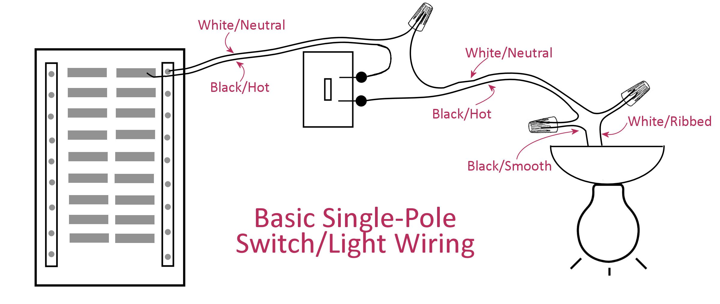
So very basically, you have a 12/2 or 14/2 wire coming from your breaker box and to the junction box where your light switch will be installed. From there, you have another 12/2 or 14/2 wire going from that light switch junction box to the junction box where your light fixture will be installed.
Side note: 12/2 simply means that the conductors are 12-gauge wire, and within the outer sheathing, there are two conductors (i.e., a black/hot and a white/neutral) plus a ground wire. 14/2 means that the conductors are 14-gauge wire, and inside the outer sheathing, there are two conductors (i.e., a black/hot and a white/neutral) plus a ground wire.
Inside the light switch junction box, the two black (hot) wires get attached to the screws on the light switch. The two white wires get attached together with a wire nut. And then at the light junction box, the two black wires (or the black from the ceiling and the smooth/solid color wire on the light fixture) get attached together with a wire nut, and the two white wires (or the white wire from the ceiling and the ribbed/striped wire on the light fixture) get attached together with a wire nut.
And that’s it. It’s really that simple.
So just for clarity, you can see from the drawing that the black/hot and white/neutral conductors form a complete circuit. The electricity flows from the breaker box through the black/hot wires, and then returns through the white/neutral wires. It’s a complete loop, or circuit. If you have a break in that circuit at any point, you will lose power. And that’s the basic concept behind a light switch. In the off position, it breaks the continuous flow of electricity in that loop or circuit, causing the light to turn off.
I’m explaining this, because once you understand the basic concepts, it’s so much easier to figure out how to do different things. Unlike my very simplified drawing above, you’ll almost never find a real life situation where the only thing on a circuit is one single light switch.
You’ll almost always have a situation where the light switch is in the middle of a circuit. Or you might need to wire two light switches in one box in the middle of a circuit. Or you might have a light switch already wired, but want to add an outlet on that same wall. Or maybe you’re wiring a four-gang box that will have three light switches and one outlet.
So having a general understanding of how, why and when the electricity flows through the different conductors will help you tackle any of those situations.
So let’s move on to my particular switch, which isn’t quite as simple and clear cut as my drawing above since I have several outlets and switches on the same circuit. But hopefully this will help you understand some basic concepts a bit more.
Wiring a single light switch in the middle of a circuit
In this first example, I’ll be wiring a one-gang junction box that holds one single switch, and that switch controls one single pendant light. And this switch is pretty much right smack dab in the middle of the circuit, with two switches before it, and a few outlets after it in the circuit.
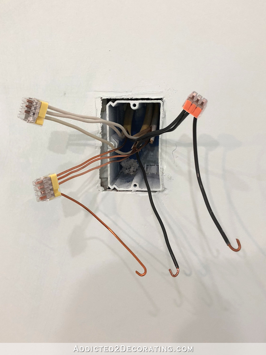
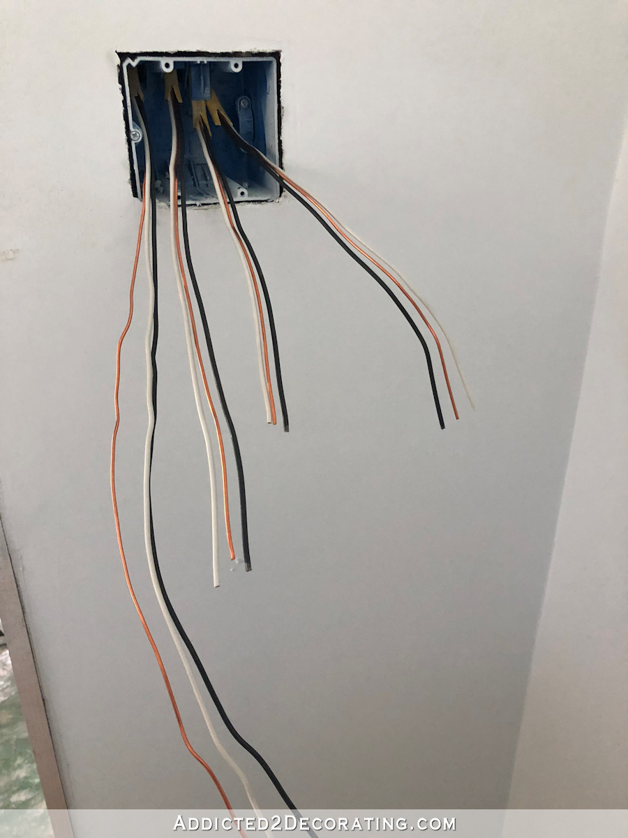
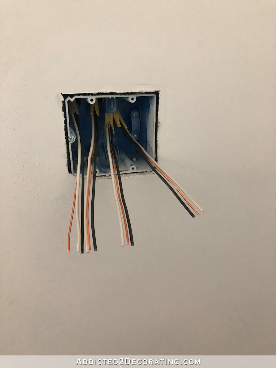
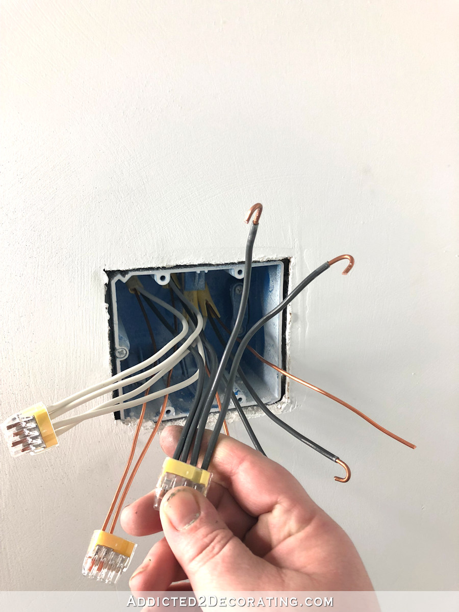
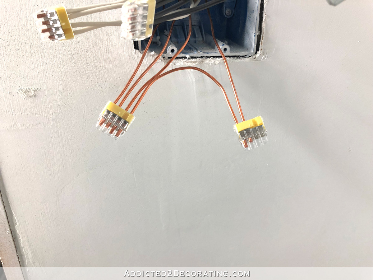
Inside my junction box, I have a black, white and ground wire that are coming from the power source (power in). I have another black, white and ground wire that are going from this box and feeding power to the next junction box (where there is an outlet) in this circuit. And then I have another black, white and ground wire that go from this box to the light fixture on the ceiling.
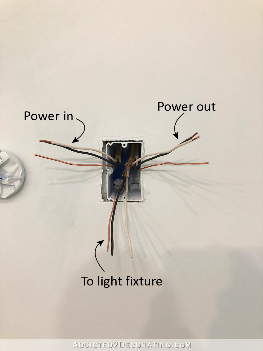
Before I took that picture, I had already stripped the yellow sheathing off of the wires, and cut the exposed conductors to six inches in length. (They need to be at least six inches from where they emerge from the yellow or white sheathing, and on small boxes like this, you need at least three inches of conductors extending from the front of the box.)
Before I even think about my light switch, I need to ensure that I have an uninterrupted flow of electricity going from this junction box to the next junction box in this circuit where I have an electrical outlet. Because if the flow of electricity coming into this box is interrupted in any way before it can travel to the next junction box where I have my outlet, then my outlet (and anything else that comes next in this circuit) won’t have power.
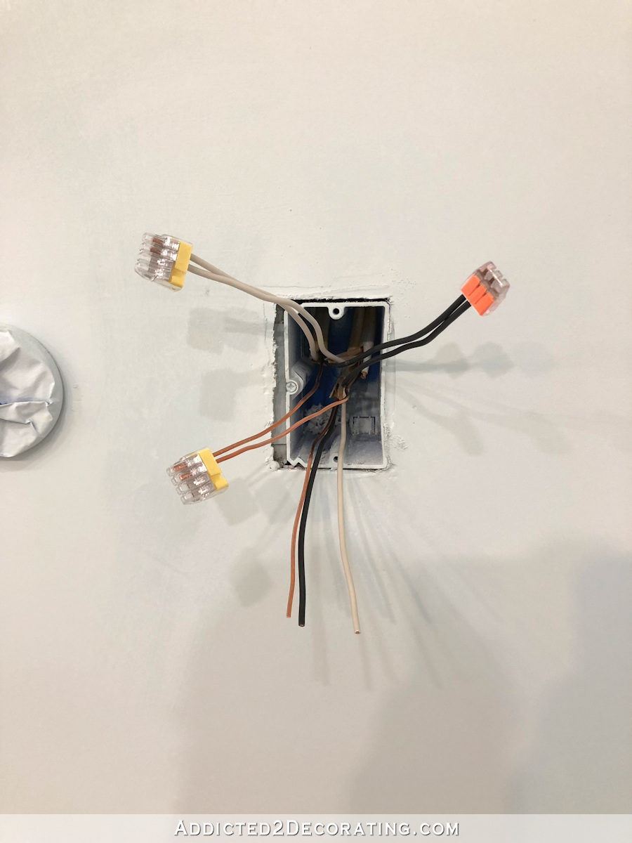
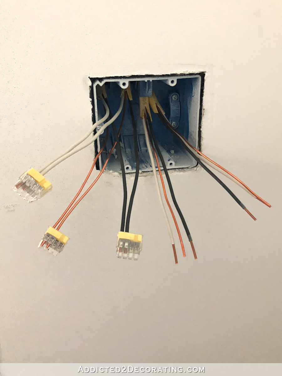
To ensure this uninterrupted flow of electricity, I simply need to connect my “power in” and “power out” conductors. I used push-in connectors because I find them so much easier to deal with than wire nuts, but you can certainly use wire nuts as well. If you use wire nuts, don’t actually attach the wire nuts just yet. But if you use push-in connectors, they’ll look like this right now, with the black (hot) wires from the “power in” and the “power out” connected, and the white (neutral) wires from the “power in” and the “power out” connected, and the ground wires from the “power in” and the “power out” connected.
Now that I’ve established an uninterrupted flow of electricity to the next item in this circuit, I can now focus on installing the light switch that will send power to the light fixture on the ceiling when the light switch is turned on.
Wiring a light switch is very simple. The white (neutral) wire from the power source and the white (neutral) wire that goes to the light fixture get connected to each other. The black (hot) wires are what get connected to the light switch.

Again, excuse my paint-covered hands. I paint a little and then work on electrical. Then paint a little, and then work on something else. 🙂
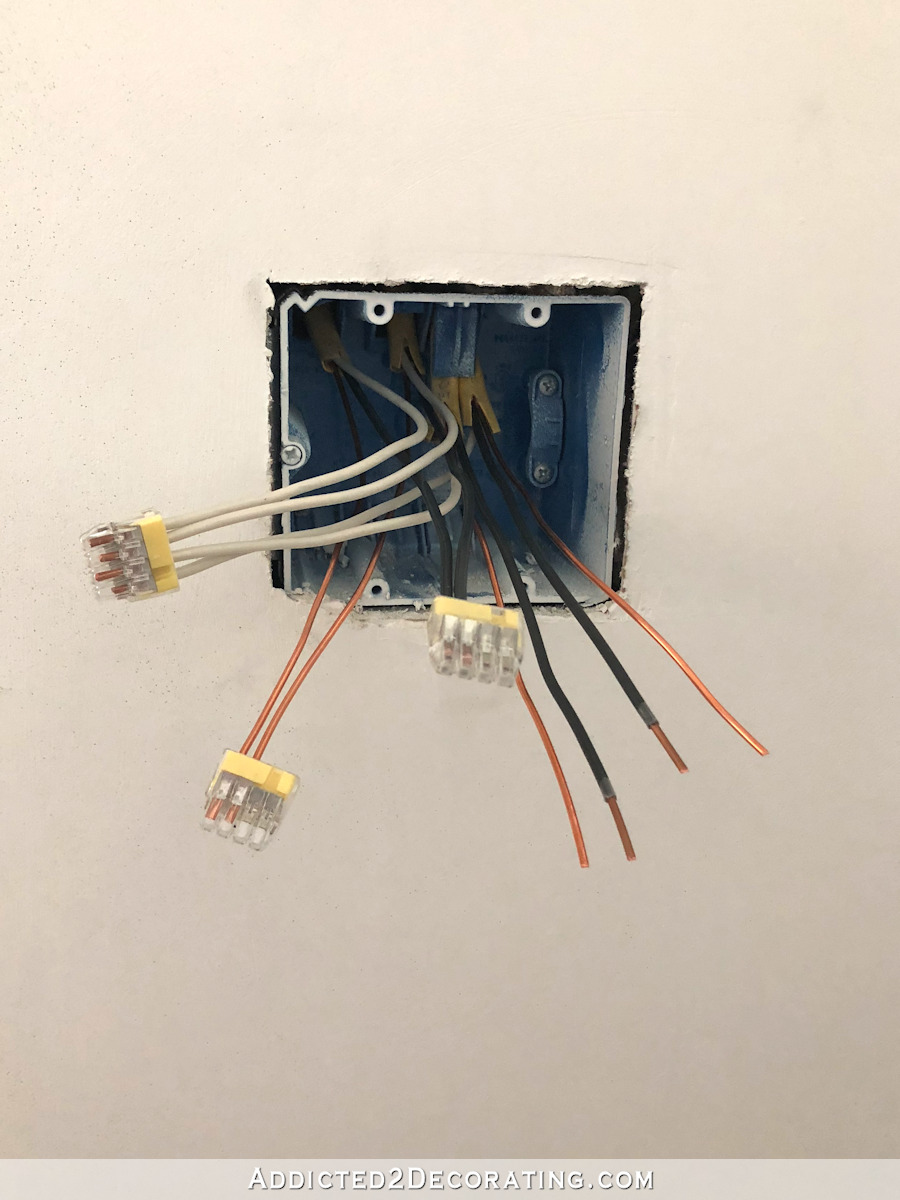
So back to the junction box. At this point, I have the “power in” and the “power out” conductors all connected, leaving the hot, neutral and ground that go from the junction box to the light fixture.

The ground wire that goes to the light fixture needs to be connected to the other ground wires…

And then the white (neutral) wire that goes to the light fixture needs to be connected to the other neutral wires…
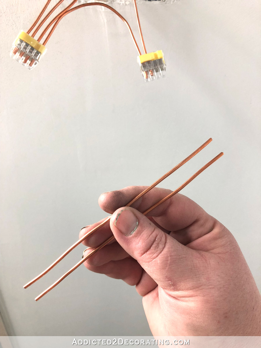
That leaves me with one black (hot) wire that goes from the junction box to the light fixture. But remember, for the light switch, we need one black wire coming from the power source to the light switch, and one black wire going from the light switch to the light fixture. We also need a ground wire connecting the light switch to the other ground wires.
To achieve this, I cut two pigtails, which are simply short lengths of conductors (six inches) that connect one thing to another inside a junction box. I connect a black pigtail to the other black wires that have already been connected, and I connect a bare (ground) pigtail to the other ground wires.
And with that, I have everything I need to connect the light switch — a black (hot) wire feeding power to the switch, a black (hot) wire sending power to the light fixture, and a ground wire.
To connect the conductors to the light switch, I stripped the ends the specified amount according to the strip gauge on the back of the light switch, and then used my pliers to create a hook in the ends. Then I wrapped those clockwise around the terminal screws so that they reached 3/4 of the way around the screw, and tightened the screws. I put the one bringing power into the light switch on the bottom, and the one sending power to the light fixture on the top.
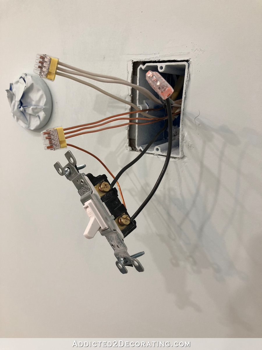
And then I hooked the end of the ground wire, wrapped it around the green screw clockwise so that it reaches 3/4 of the way around the screw, and tightened.
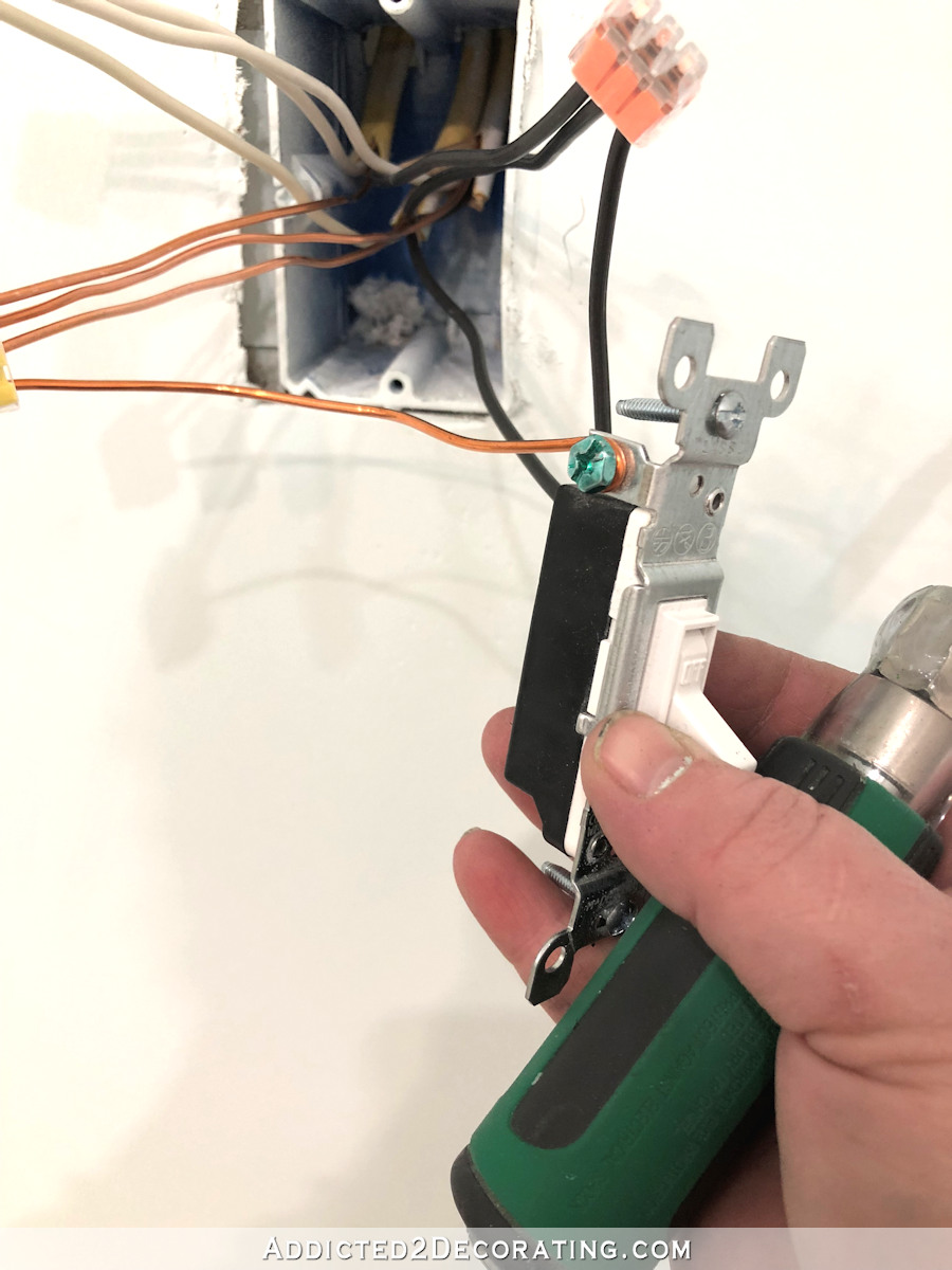
And with that, the light switch is ready to be screwed onto the junction box.

It takes a little patience, especially when dealing with 12-gauge wires, to get those things wrestled into the box. You just have to be firm but careful that you don’t damage anything, and once the switch is screwed onto the box, be sure that nothing is touching the screws
Does it all make sense? Let me break it down very simply:
- You need an uninterrupted flow of electricity coming into the box and then going to the next item (a switch or outlet) in the circuit. To do this, the “power in” and the “power out” conductors need to be connected.
- Then you need to feed power to the switch which will turn the light fixture on and off. To do this, the white (neutral) conductors from the “power in” and the “to the light fixture” wires need to be connected to each other. Then the black (hot) conductors from the “power in” and the “to the light fixture” wires need to be connected to the light switch.
- And finally, the light switch needs to be grounded.
Wiring two switches in one box in the middle of a circuit
Now I’ll show you how to wire two light switches in the same box (i.e., a two-gang box). And again, these switches are located in the middle of a circuit. So just keeping the same concepts in mind, this is what we need to do:
- Establish our uninterrupted flow of electricity from this box to the next item (switch or outlet) in this circuit.
- Then from that power coming into the box, feed power to each light switch.
- From those light switches, feed power to each light fixture.
That’s the basic concept, so let me show you step-by-step just how I did that.
I started with these four wires coming into the box. From left to right, I have power in, power out, to the ceiling light, and to the wall (vanity) light.
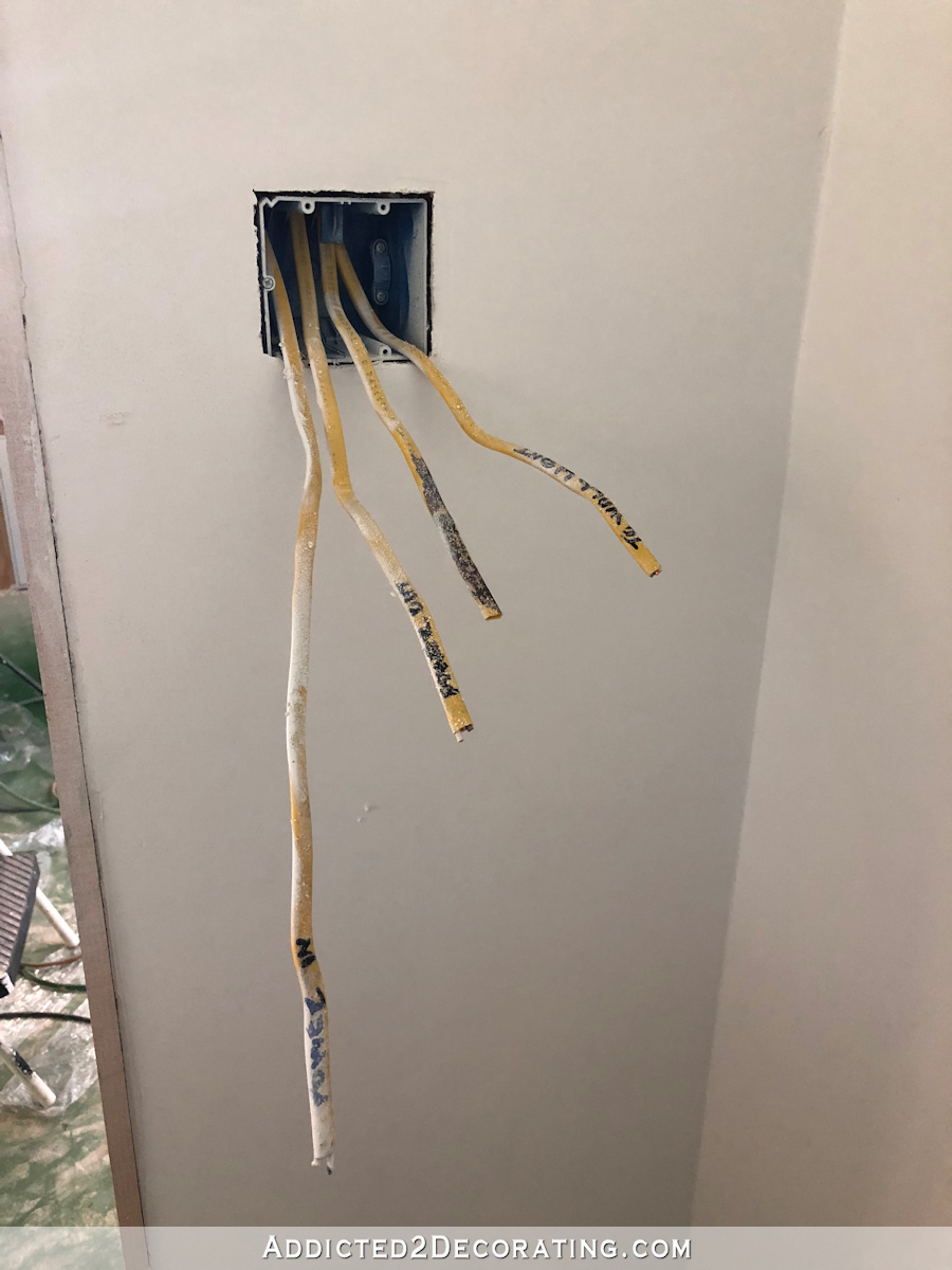
First, I strip the yellow sheathing from the conductors…
And then I cut the conductors to length. They need to be at least six inches from the point where they emerge from the sheathing, and there needs to be at least three inches of conductors extending past the front of the box.
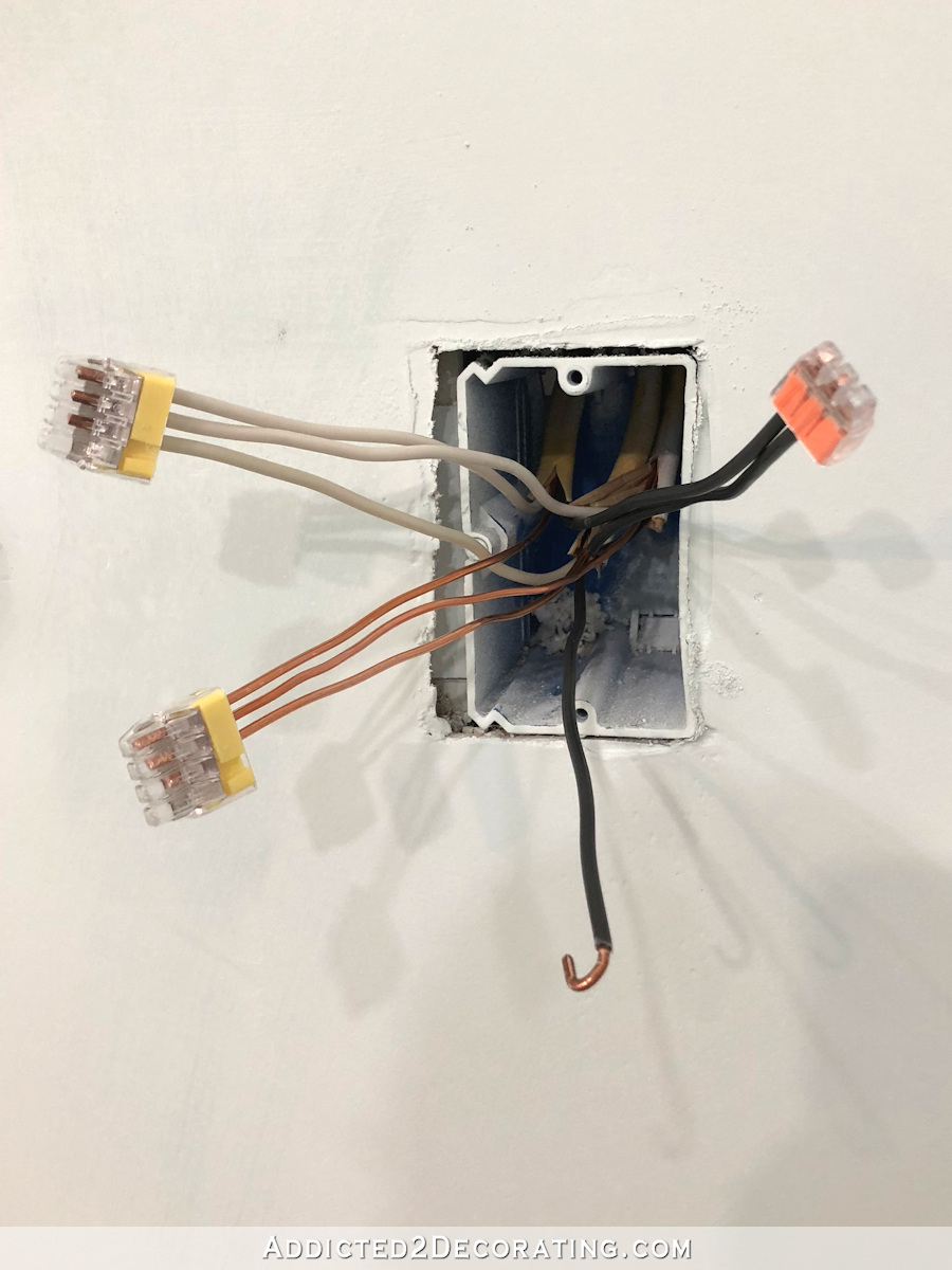
Before even dealing with the switches, I first need to establish my uninterrupted flow of electricity from this junction box to the next junction box in the circuit. I do this by connecting the white (neutral) wires from the “power in” and the “power out.” Then I connect the black (hot) wires from the “power in” and the “power out.” And finally, I connect the bare (ground) wires from the “power in” and the “power out.”
Now that I’ve established that uninterrupted flow of electricity to the next junction box, I can turn my attention to the switches and the wires that go to the actual light fixtures.
The first thing I do is connect the white (neutral) wires that go the light fixtures to the other white wires.
That leaves me with two black (hot) wires — one wire that goes to each light fixture. But remember that each switch requires two blacks — one bringing power in, and one sending power to the light fixture. Right now, we only have the ones sending power to the light fixtures.
So to remedy that, I cut two black pigtails that are six inches long…

…and I connect those black pigtails to the black conductors that are already connected…
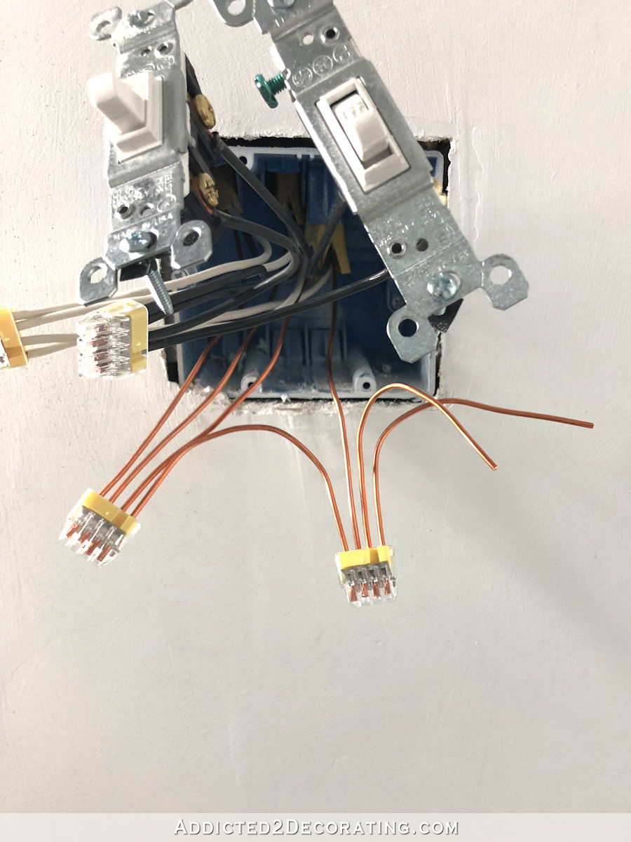
I now have what I need to bring power into the switches, so I connect one pigtail to the bottom screw on each of the switches.
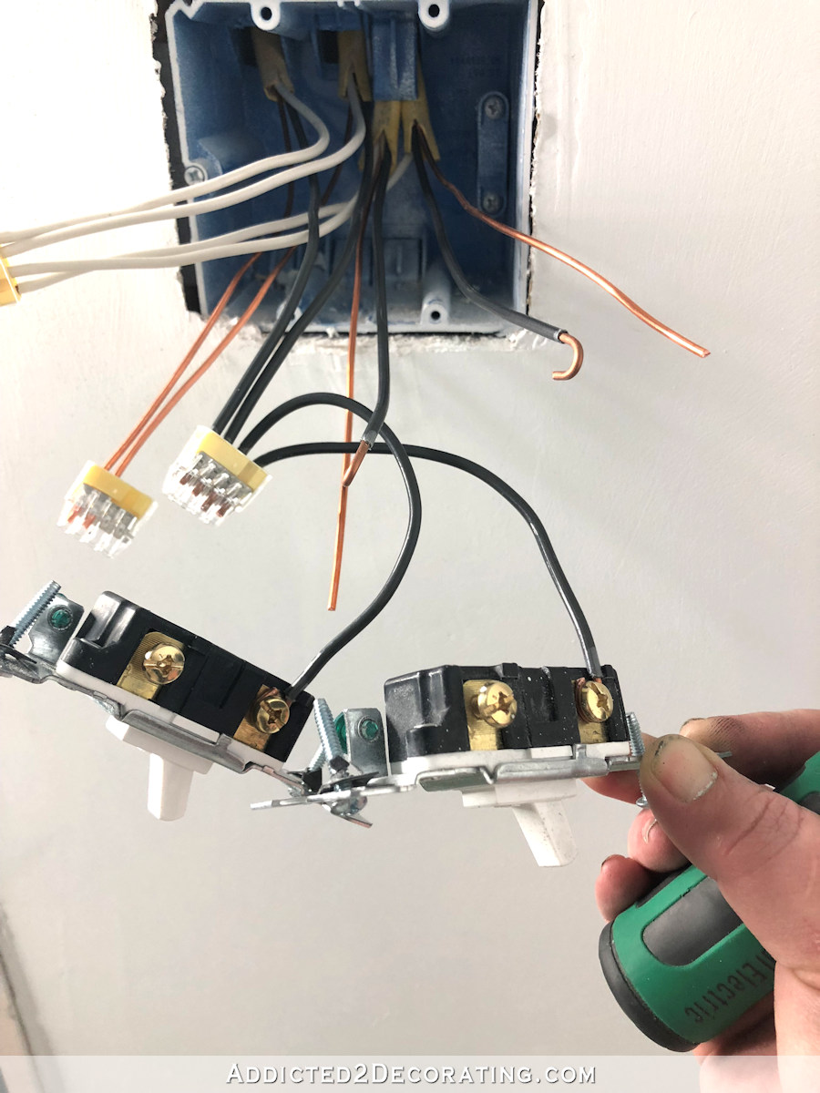
I’ve now established power into the switches, so I need to send power from the switches to the light fixtures. So I connect the other two black wires to the top screws on the light switches.

So at this point, my neutral wires are all connected, and I have power in (from the power source) and power out (to the light fixtures) on each switch. But the switches still need to be grounded. I have the two ground wires that go to each light fixture, and only two more slots in my connector.

But I need space for four more ground wires, because I have the two that go to the light fixtures, and then I need two for the light switches (one for each switch). So I go ahead and connect one of the remaining ground wires to the connector…
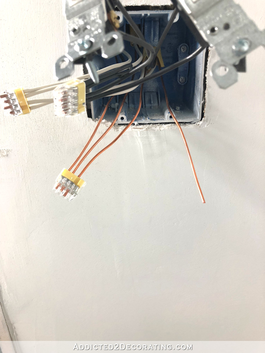
But then I need to cut a pigtail to act as a jumper from this connector to another connector to make room for the other neutral wires.

So after using that pigtail as a jumper from one connector to another, it looks like this…
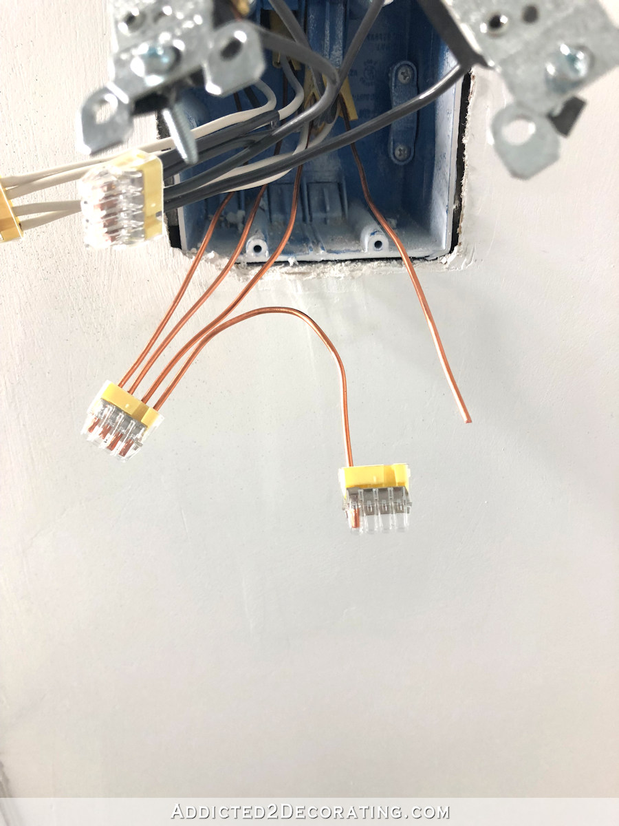
Now obviously, if you’re using wire nuts, you don’t need a pigtail to act as a jumper. You’d just connect them all together and make sure you use an appropriately-sized wire nut to connect all of those wires together. But since I’m using push-in connectors, and there are only so many slots in each connector, I have to use a pigtail as a jumper.
And with the two now connected, I can add the rest of the ground wires I need to the second connector. I start by adding the other ground wire that goes to the second light fixture…
But I still need to ground the actual light switches. I do this by cutting two bare wire pigtails that are six inches long…
I put those into the connector…
And then attach one ground wire to each of the light switches.

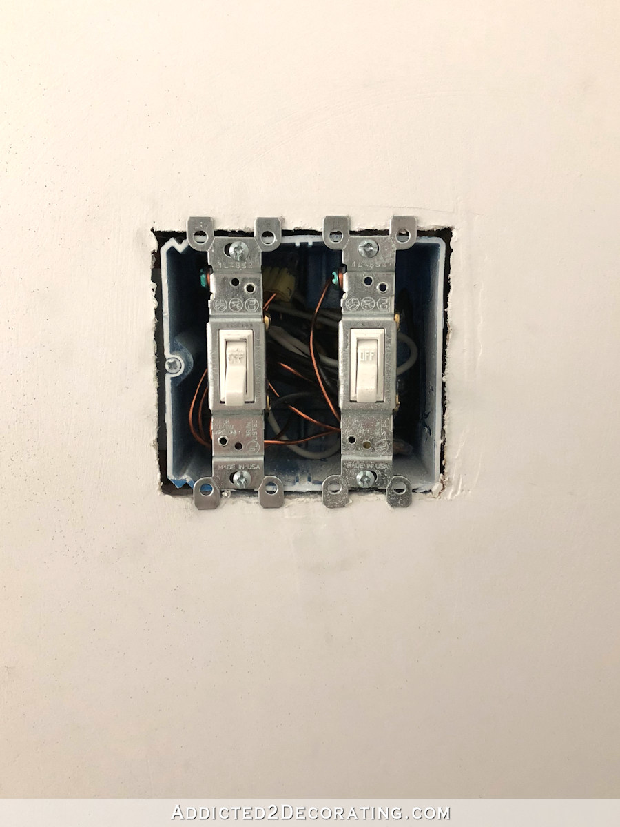
And voila! Done!
Then I just have to coax those wires into the box, carefully but firmly, screw the light switches to the box, and make sure that nothing is touching the screws on the sides of the switches.
To wrap up…
I know this was long, but I hope it helped some. I know when my father-in-law came to town and we (or rather, he) wired the living room, I was so lost. I have a four-gang box with four light switches just inside my front door, and for the life of me, I couldn’t figure out how he had wired all of those so that each light switched off and on like it should, while the electrical outlet that was down the line on that circuit still had power all the time.
Y’all, it took me forever to understand it. I felt like I had a complete mental block. But then one day, I finally got it. Everything just clicked in my mind, and I finally understood.
I finally understood that first, before wiring any of the switches, you have to establish uninterrupted power from the junction box that you’re working on, to the next junction box in that circuit, whether it’s an outlet or another switch. And then after you’ve done that, you have to bring power into each light switch, and then send power from each switch to each light.
Once the concept was simplified in my mind, I was able to wire up just about any configuration I came across — a four-gang box with all switches, a three-gang box with two light switches and one outlet, and on, and on.
I’m telling you. A knowledgeable homeowner is an empowered homeowner, whether you use that knowledge to do the work yourself, or whether you use that knowledge to give valuable input to your electrician as to how you want things done that will affect your daily life for years to come.

Addicted 2 Decorating is where I share my DIY and decorating journey as I remodel and decorate the 1948 fixer upper that my husband, Matt, and I bought in 2013. Matt has M.S. and is unable to do physical work, so I do the majority of the work on the house by myself. You can learn more about me here.


Wow that is so thorough and helpful. I’m so glad that you are tackling this electrical stuff. Some of the basics don’t seem that tough and it makes me feel much better seeing that you are doing it. I’m hoping you also have a post on basics of wiring a light fixture. If not, I’d love to see that next since I’m planning to replace a bunch in my house.
Wow! This is great, Kristi! an amazing tutorial and the clearest I have ever seen. I thought I understood how it was done before, but separating and doing the through circuits first makes so much sense. Those click connectors are cool, we used wire nuts long ago. Getting all the wires pushed back in the box is sometimes a bear.
Have you ever done a blog post with your history of how and where you learned all this? I’m fascinated by the breadth of your knowledge.
I *think * I understand now, with this great explanation, but I’ll have to re-read it many times over. I thought I had it until the last paragraph where you spoke of “uninterrupted power.” Does that mean no other switches/boxes can be on the same wire? Would you be running separate wire from the breaker box? Maybe I need to go back to your other post where you wired the entire space. This is my confusion, so I will keep studying, even though I know I will never actually do electrical unsupervised! You are an amazing teacher, I’m just trying to make it harder than it is I think! Heck, I still don’t get the grade school science where you can light a light bulb with a battery! LOL! Science and Math were always my downfall.
A very nice spot on and informative write-up. If I may for the benefit of your readers be allowed to toss a few tidbit of information out there.
In a home you’re likely to come across four possible types of light switches; a single pole, a 2-pole, a 3-way, and a 4-way. Excluding the ground screws on all of these switches, a single pole has 2 terminals, a 2 pole has 4, a 3-way has 3 and a 4-way has 4. The most notable way to identify if a light fixture is turned on from only one location without taking anything apart is to look at the switch itself. Both a single pole and 2-pole switch will have the words “OFF” and “ON” on the handle, while both 3 and 4 way switches do not.
The difference between a single and 2-pole switch is a 2-pole is nothing more than two single pole switches built into one device. This type is useful when two different circuits have to be turned on together, such as when one circuit powers a bathroom light and a different circuit powers an exhaust fan. If both the light and fan are power by the same circuit then a single pole switch will do. A 2-pole is also necessary when controlling a 240 volt device such as an air conditioner. For the 3 and 4 way switches, two 3-ways switches are requires when there are two different location to turn on one light fixture, but when there are three or more locations, each additional location beyond those first two require a 4-way switch.
Just curious what the bigger picture will be once the studio is complete. I’m sure you aren’t one to run out of projects, but will you be using the design space to take on outside clients? I hope the are agreeable to sharing your amazing transformations on the blog 🙂
I may take on outside clients when I finish my own home, but I have no immediate plans to do that right now. But I could very well change my mind tomorrow. 🙂
Kudos to you for taking on a DIY wiring project! I like your caveat that the typical homeowner should not attempt ALL household wiring – I mean common sense says there’s an inherent risk by doing so, but this post is great for those DIYers who naturally shy away from simple wiring projects. And bonus, I love that this post was written by you, a woman – it reinforces the idea that a woman’s role is not limited to only beautifying a home, but to include making it functional as well.
Very well written. I appreciate you explaining concept and then walking through each step. Explanation of switch leg would be helpful