Electrical Wiring Basics Part 2 – Wiring A Circuit
Last year, I wrote a post about the first steps in how to wire a room, including info on circuit breaker panels, what a circuit is, and all of those basics. If you missed that post, or want to refresh your memory, you can find that here…
This isn’t really exciting stuff, but I know many of you were interested in learning the basics. And even if you’re not looking to rewire your house, I do believe that information is empowering. And it’s a good thing for homeowners to understand how things like electrical circuits work.
NOTE: This isn’t necessarily intended as a tutorial, but is more for removing the mystery and helping you understand how this very important part of your home works. Take caution if you choose to do any wiring on your home. Before starting, you need to check local building codes, local requirements, etc. All counties have different and specific requirements, so check with your local building permit office.
Since I’m currently working on my studio, I want to show you how I wired one of the five electrical circuits in my studio. I think you’ll be amazed at how simple this is. But let me start with a quick refresher…
What is an electrical circuit?
An electrical circuit is simply a series of outlets and switches that are fed by one continuous electrical current coming from one circuit breaker in the breaker box of your home.
Here’s a peek at my circuit breaker panel…
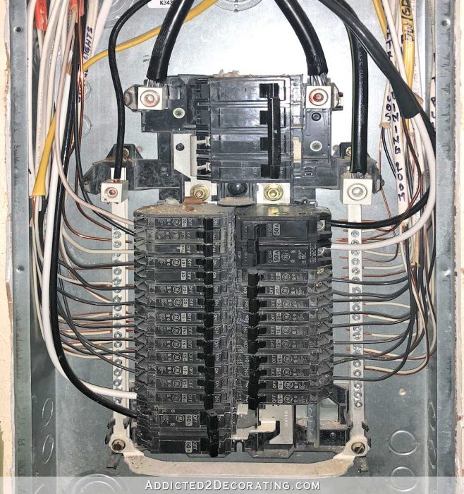
And you have something like that located in your home as well (unless your home is still using a fuse box, in which case I would recommend looking at an upgrade as soon as you can).
Each one of those little black switches powers one circuit. So right now, it looks like my house is divided into about 24 regular circuits. (Those big bubbas are for major things like the HVAC system, so I don’t mess with those.)
So when planning the electrical wiring for the studio, I planned for five additional circuits. That means that five main wires needed to come from that main circuit breaker panel (which is located in the closet of the guest bedroom at the opposite end of the house). Those five separate wires will eventually be connected to five new circuit breakers that I’ll add in that panel. But for now, they’re not connected, so these wires have no power going to them just yet.
Those five wires needed to go from that circuit breaker panel, up into the attic, across the entire attic, and into the studio.
So for the last several months, those five wires for the five circuits have just been draped over the studio wall and hanging in the room. You can see all five wires here…
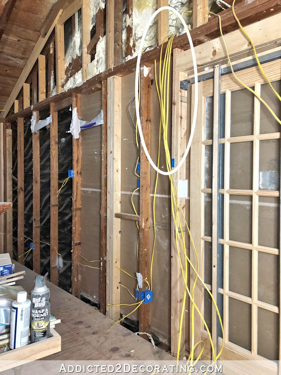
And again, those are not connected to the circuit breaker panel yet. They have no power going to them right now. I can safely work with these wires, cut them, and do what I need to with them with zero chance that I’ll get hurt, because they have no electricity going through them.
Obviously you can’t have wires draped over a wall like that, so they’ll eventually all have to be fed through the walls and to the outlets and switches that they need to power. So let me show you how I wired one circuit in the room.
How an electrical circuit is wired.
The concept is very simple. I promise. 🙂 And this is it…
For each outlet or switch in a circuit, there has to be POWER IN (i.e., a wire coming into the outlet/switch to give it power), and there has to be POWER OUT (i.e., a wire going from that outlet/switch and going to the next outlet/switch in the circuit).
The only exception is when you reach the last outlet or switch in that circuit. In that case, it will only have a POWER IN (i.e., one wire coming into the outlet/switch, but nothing going out).
So I’ll show you how this very simple concept works in real life.
First, I already had all of my five main wires for the five separate circuits labeled for where they needed to go. I selected the wire I needed according to the label. After determining the first outlet/switch that needed to be powered by this circuit, I drilled a hole in the top plate of the wall just above the first outlet, and fed the wire through.,
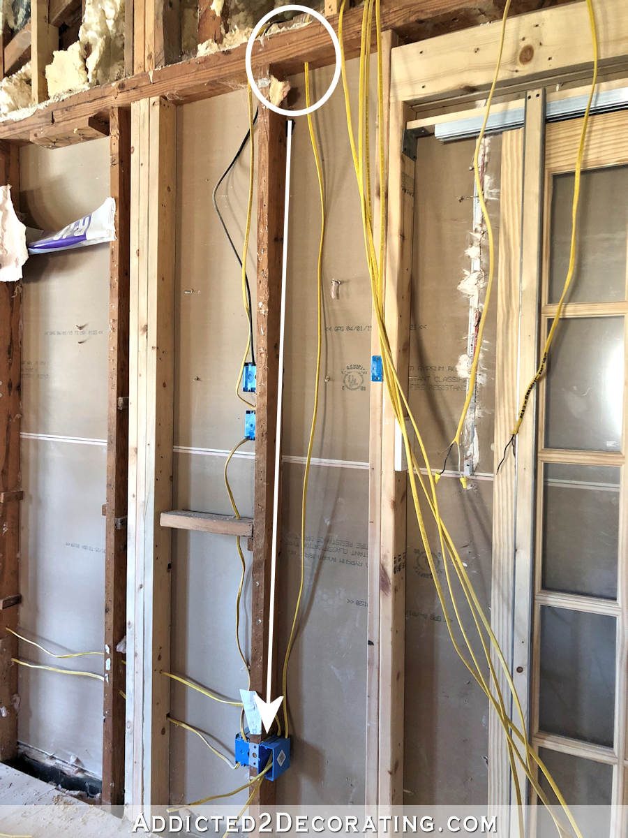
Then I fed that wire through the junction box for the first outlet in that circuit, as indicated by the arrow above. That gave me POWER IN to that outlet.
Then I needed to run a wire from that first junction box to the next outlet in the circuit, which is the outlet for the TV that I’ll eventually hang on that wall. So I ran a separate wire from the first outlet (i.e., POWER OUT), to the TV outlet (i.e., POWER IN).
Here are those two wires highlighted in orange and pink so you can easily see them.
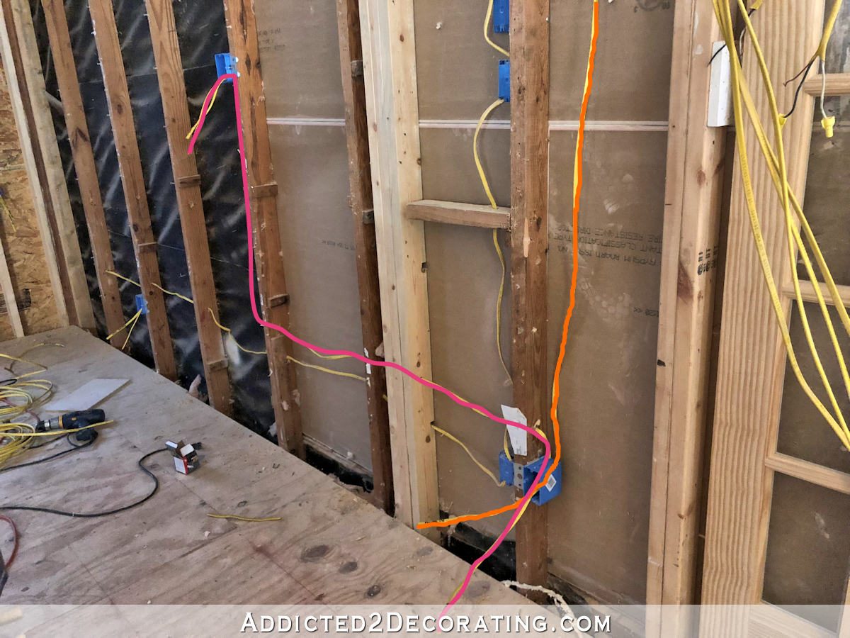
The orange comes from the main wire that goes from the breaker box panel and through the attic, and gives POWER IN to the first outlet. The pink goes from the first outlet (POWER OUT) to the second outlet (POWER IN).
And I always, always, ALWAYS label my wires.
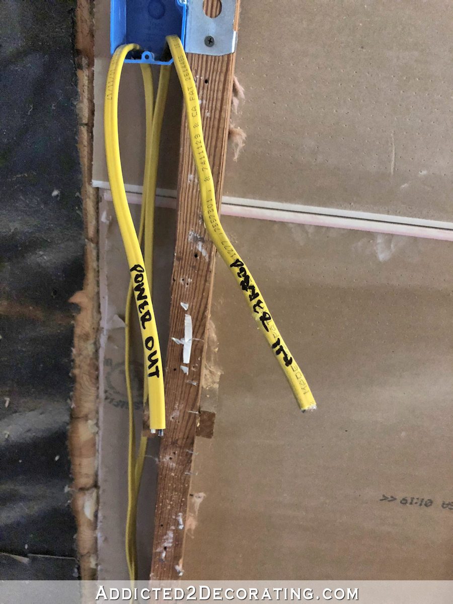
When you’re wiring a circuit that’s all outlets and no switches, the labeling really isn’t that important. But when you mix switches in, the labeling becomes important, as I’ll show you later. So I just get in the habit of labeling every single wire, no exceptions.
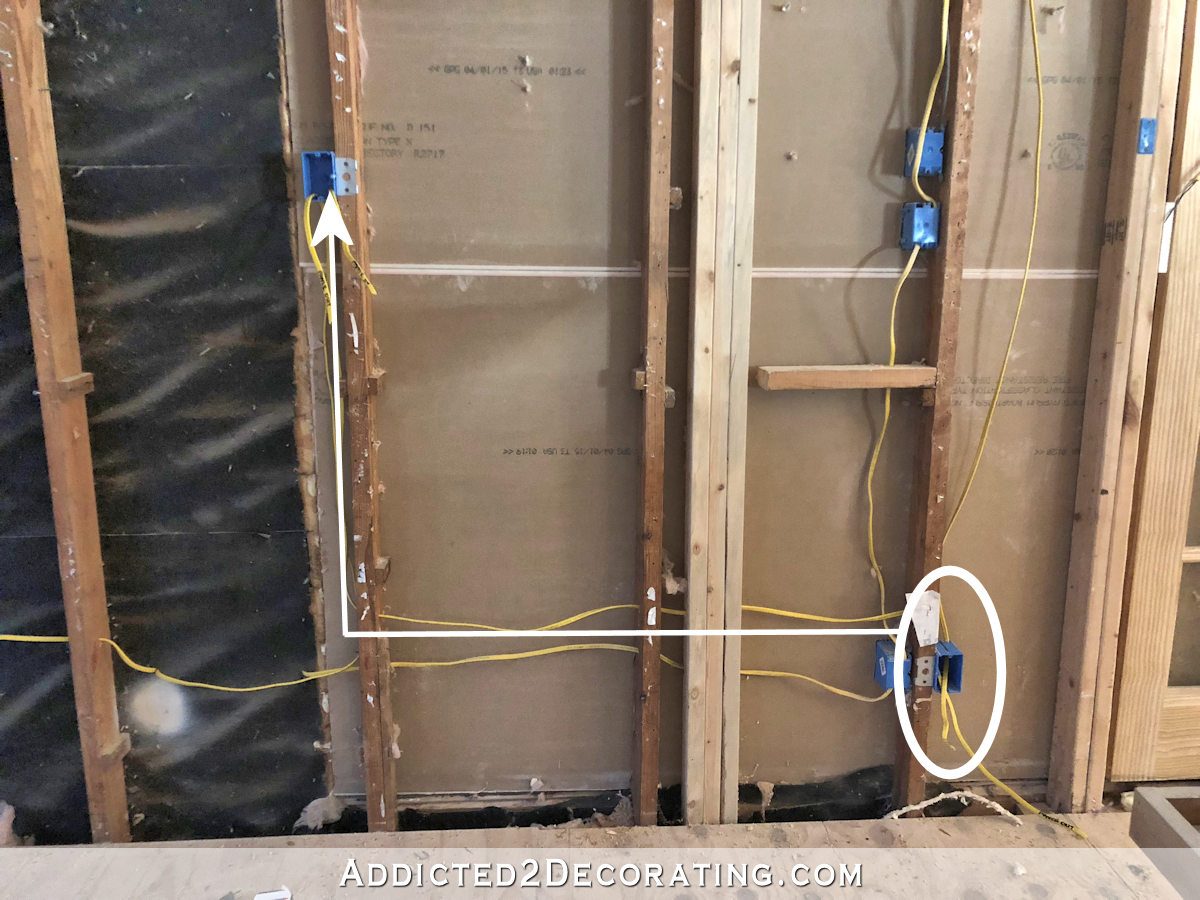
So from that TV outlet, I ran another wire from that outlet (i.e., POWER OUT) to the next outlet in that circuit (i.e, POWER IN). You can see it indicated by the pink line below.
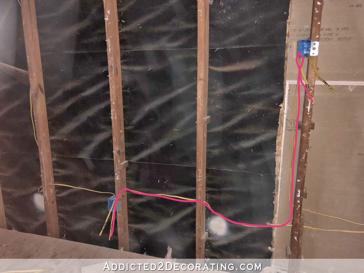
And really, it’s as simple as that. You just keep going until you reach the last outlet or switch in the circuit, and in that last one you’ll only have one wire going in, with no wire going out.
Wiring Switches For Lights
So as you can see, wiring a circuit of outlets is super simple and pretty straightforward. Wiring lights is also simple, but it does require more steps.
For switches, in addition to the POWER IN and POWER OUT wires, you also have to have a wire going from the switch to the actual light. I mean, that’s obvious, right? 😀 You can’t really switch on a light if it doesn’t have power going to it.
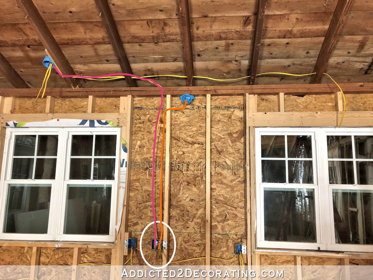
So on a junction box that will contain a switch (or two switches, in my case), I have the usual POWER IN coming from the previous junction box on the right. And I have the POWER OUT feeding the next junction box on the left.
But I also have two more wires going out of that junction box. One goes from the switch to the junction box where I’ll have a wall sconce (highlighted in orange below), and the other goes from the switch to the junction box where a pendant light will be hung (highlighted in pink below).
And because I’m going to have two pendant lights that turn on with one switch, I also ran a wire from one pendant light junction box over to where the other pendant light will be. (I’m missing a junction box right now, but it’ll be added soon.)

And this is where that labeling comes in handy. I don’t have to guess at what these wires are, because I have them clearly labeled POWER IN, POWER OUT, TO SCONCE, and TO PENDANTS.

So that is one of five circuits that will give electricity to my studio, half bath, back entry, and closet.
It’s really simple when you think about it, right?
Every outlet/switch needs POWER IN, and unless it’s the last one in the circuit, it also needs POWER OUT to feed electricity to the next outlet/switch in the circuit. And if it’s a switch, you also need a wire from the switch to the light that the switch will be powering.
Simple stuff!
And that’s actually where you stop in a room that hasn’t been drywalled yet. I’ll just roll up these wires and tuck them into the junction boxes so that they’re out of the way for the drywall guys. Then after the drywall is up, I’ll go back and wire up the actual outlets and switches. It’s just easier for them if they don’t have to work around the actual outlets and switches. And I’m nothing if not accommodating. 😀
And after the drywall is installed, and the outlets and switches are installed, and the lights are installed, that’s when I’ll go back to the circuit breaker box and wire each of those five wires to the five separate circuit breakers. Then the room will actually have electricity!

Addicted 2 Decorating is where I share my DIY and decorating journey as I remodel and decorate the 1948 fixer upper that my husband, Matt, and I bought in 2013. Matt has M.S. and is unable to do physical work, so I do the majority of the work on the house by myself. You can learn more about me here.

I love these posts. You explain things very simply and well. I’ll take all of it you can give me.
My husband and I have switched out all my fluorescent under the cabinet lights for LED . I also have over the cabinet fluorescent lights. I would like to
Change those for LED tape lights. I went to the Lowes and Amazon web sites to look for LED tape like you put on your front porch. I did not find hardwire type only plug in. There is no plug over my cabinets. Do you think the tape lights will be a good substitute for over cabinet lighting? How do we change from plug in type?
I bought the kind with the plug and hardwired them. I just cut off the plug (making sure I didn’t cut off the transformer!!), and hardwired.
Thanks so much for this post, Kristi! Just wondering how many boxes can you wire until you get to the last one. Is there a limit? I guess that might depend on what will be plugged in, right? I know my refrigerators and freezers had to have something special wired for them. At some point, I’ll need to wire my basement, so this will come in VERY handy!
Always research building codes (national as well as local) for specifics before doing any work, but the general rule is that you should limit circuits to about 10 outlets. There are certain things in your home that will have dedicated circuits that can’t (or shouldn’t) be shared with anything else. My refrigerator has it’s own circuit. As does the HVAC system (which I would never recommend as a DIY project — leave that to the pros). My pantry freezer is on its own circuit, as is my clothes dryer.
Thanks, Kristi!
Thanks Christy! This makes it so easy to understand. I’ve always been afraid of working with electricity and plumbing, but this is a big help. I feel braver already!
Oops. Kristi! Must stop multi tasking.
You are AMAZING!! This weekend I was so happy to have switched out light fixtures in my studio/office with my husband cheering me along. Maybe one day I will have a reason to refer back to your post and I’ll spread my wings to do some actual wiring. This is definitely is empowering. Plus, I remember having a schematic for my house when it was built and the electrician kind of did what he wanted and I didn’t realize it until after the drywall was installed. Whether we do the work ourselves or not… we can surely understand the process and be smart about it. Thanks, Kristi!
For home insurance purposes, aren’t you supposed to have a master electrician do this type of work?
Again, you have to check with your local building permit office for your county’s requirements.
My husband and I built our house and did all of the wiring except HVAC. Once it we all done we had it inspected and signed off on by a licensed electrical engineer and then inspected.
When my partner and I were building we could run the wiring from room to room but installing the panel and breakers had to be done by a professional and everything inspected by the municipality before the drywall was put up.
Awesome and informative post! Recently my under cabinet lights in the kitchen stopped working. They were professionally installed 13 months ago and the switches were changed to wide rocker switches. A can light over the sink, controlled by the same switch, was flickering. It ended up costing me $200 to find out a wire to the switch was loose. It’s a mystery why it worked for 13 months. It was not disturbed during that time. But…I wish I had known enough to fix it myself. I also thought the electrician should have taken some responsibility for the problem since he wired the switch. Clearly it was not connected securely. But I wonder if the wide rocker switches cause more jarring than regular switches. Kristi, your ability to tackle and complete these huge projects is awe inspiring.
My husband and I built our house and did all of the wiring except HVAC. Once it we all done we had it inspected and signed off on by a licensed electrical engineer and then inspected.
Finally! YAY! I have been waiting for this. So well explained.
My husband is so afraid of electricity he won’t try anything but thanks Kristi for giving me the courage to try. You are awesome! Thanks
Very well done post! Great job!
Hello Kristi.
I’m new to your blog and I wanted to tell you how wonderful your use of color is. I personally adore teal in any tone or shade. Happy and soothing. Kitchen is dynamic and beautiful. Oh and the new bathroom color is wonderful. Keep up the wonderful work. Thank you for inviting me into your home.
Where we live, all of that wiring has to be inside conduit. Definitely makes it more costly and more difficult to do DIY. I’m lucky I have such a smart and wonderful husband who tackles all of this kind of thing. I’m glad you empower a lot of women to try things themselves, but I’m just as glad this is the kind of thing I don’t have to learn how to do.
And that’s exactly why I say that people have to check local codes. Conduit isn’t required here, but I know in many parts of the country, it’s required. In some places, it’s required only in attics, and in other places, it’s requires all throughout. That’s why it’s so important to know the specific requirements in your city/county.
Advice to anyone at the wiring stage of construction— take photos of every wall and ceiling. When the drywall guys did our house, they forgot to cut out one of the outlets by our fireplace. ( I specifically asked for this outlet so I could add Christmas lights on my mantel!) Since we had taken photos, I just e-mailed them to the builder indicating what had happened, and it was easy for them to locate exactly where the outlet was so they could take care of it. And flooring guys missed cutting out a hvac vent in the master closet, but photos helped locate that too! We’ve referred to photos to locate many things behind walls over the years that we had figured we would remember, but as the years go by, memory isn’t as accurate!
I was going to add the same comment – if you have a chance, take pictures of all the wiring before you drywall. We just added a new room and got pictures so we’d know exactly where everything is in case there’s a problem later, or we need to add anything, or hang large items on the wall, etc.
I had no idea! Thanks for explaining in a way I can understand.
I love your blog! So inspiring the stuff you’ve taken on and I really love watching the progress.
I just wanted to add a little clarification (sorry, it’s the electrical engineer in me). Every outlet in your chain has a power in and a power out, that’s what the two conductors are in your wire. So, power comes in through the black/hot wire and returns to the panel through the white/neutral wire. All the outlets strung together make one big loop from the panel to all the outlets and then back to the panel. This becomes more obvious when you think about how switches are wired, the hot will travel through the switch (and the switch will make or break this connection), then to the light and then travel back to the panel through the white wire, which is why the whites will just be wire-nutted together in your switch box.
I’m gonna guess you already know all this, and are just speaking in the simpliest of terms. But either way, just figured I’d try my hand at explaining. Because when things get more complicated than just a string of outlets, it’s definitely helpful to think about the circuit in terms of the loop that it is. Those electrons need a path back to the panel to flow. =)
Again, love the blog so much!
This post is amazing! I actually understand everything you explained, although I waited a week to read it all with a cup of coffee after a good night’s sleep. Men can be so dismissive, thank you for empowering women with all that you do and teach.
I hate you were injured but so glad you are okay. You’re super important, please stay safe!